
When designing my radios I always make extensive use of Mike Peebles and Dan Petersen's "Professor Coil" spreadsheet. This tool along with the many tutorials and explanations online have vastly eased the design work around homebrew coil winding. We can now model a coil with good accuracy prior to the actual job and thus better match the coil to the other components we plan to include. One quickly becomes aware that most coils for the broadcast band vary around a nominal 220 or so uH. More than this and most variable capacitors will have too much bottom-end capacitance to tune the top of the band. Less than this and you need caps with fairly high values when fully meshed, 500+pF or more.
All the above is pretty straight forward. On the other hand, when I have been reviewing double-tuned set designs, I often note that the coil used for the ATU (antenna tuning unit) will have an inductance quite a bit lower than the main tank coil. Professor Coil doesn’t address this aspect of coil design and I have found little discussion online concerning ATU design. Mostly this seems to be dealt with in passing or as a digression when dealing with other subjects. The most useful web sites for addressing this aspect of crystal set design include Dick Kleijer's excellent work and Ramon Vargas's detailed analysis of the "Tuggle Front End", that’s about it. Neither site discusses the ramifications of varying different parameters such as the Earth Resistance, Coil Inductance, etc although Kleijier's site includes a great calculator page to allow one to ask these questions. In my explorations of ATU design (primarily Tuggle) I have made extensive use of Kleijier'e page and for this I am deeply in his debt. My hat's off to Dick, thanks so much.
The following discussion presents the results of many models cranked through the design calculator. I wished to understand what factors play main roles and which have minor parts.
For a conventional detector-circuit coil one can pretty much control all the main factors, really only the inductance and capacitance of the circuit. The main and only surprise comes in the form of "stray capacitance" resulting from the spacing of the coil wires. This can readily be 1) guessed at and 2) minimized by good coil winding technique. For the antenna circuit by contrast many of the needed parameters, earth resistance, antenna capacitance and inductance, and antenna resistance in the forms of actual wire resistance and radiation resistance are, for most of us, unknown and only guessed at. The following figure illustrates the antenna and ATU with a list of the main "components" that need to be understood and/or modeled.
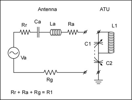
The Antenna consists of an AC voltage source (the signal of interest) Va, in series with some radiation resistance Rr, antenna capacitance Ca, antenna inductance La, antenna resistance Rr, and finally a ground resistance for the return path to complete the circuit. In addition the ATU consists of a coupling capacitance C2, and a tank with inductance L1 and capacitance C1. The capacitance and inductance of the ATU is needed to tune out the reactance of the various components of the antenna for which we do not have data. What to do?
Without an antenna analyzer (expensive) one can only estimate the many component values based on published antenna models. Ken Kuhn's engineering page has a number of nice models and a good discussion of the antenna parameters we will be trying to understand and use. For my personal setup my antenna consists of about 75' of 14awg wire averaging about 10-12' high and with another 25' of lead-in. For such an antenna Kuhn models a 30m antenna 3m high which approximates my situation closely enough. Wire resistance is negligible as is the radiation resistance which he shows to vary between some 0.1 to 1.5 ohms. Such an antenna is capacitive by nature and will have about 220 - 375pF along with some small 20uH inductance, not too far off a standard "dummy" antenna. This pretty much leaves earth resistance Rg and the main unknown parameter.
For Rg one has the option of punting and taking the "Standard" value of 25 ohms. In my modeling I have found this parameter to be critical and highly sensitive. I do not recommend guessing here, it is recommended one go to the internet page of their state, county, or local government and search for reports on ground or soil resistivity (or conductivity). As this is an important agricultural and engineering parameter, it has been surveyed for most places and should be available with some effort. Effort well rewarded. Earth resistivity for the Texas Gulf Coast is a mercifully low 10 - 15 ohm meters, but for many regions this will not be the case.
Earth resistivity depends on a number of variables including the material, moisture, mineral salt, and temperature. A table of typical ranges in ohm meters for some different soils follows:
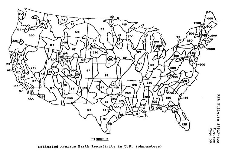
		Loam 		5 - 50  ohm meter
		Clay 		4 - 100
		Sand/Gravel 	50 - 1,000
		Limestone 	5 - 10,000
		Sandstone 	20 - 2,000
		Granite 	1,000 - 2,000
		Slates 		600 - 5,000
Moisture up to about 17% dramatically lowers resistivity, mineral salts are needed as pure water is an insulator, and as the temperature approaches freezing the resistivity also rises dramatically. All these factor into your estimation of Rg. The actual resistivity seen by the circuit depends on the earth resistivity and the type of grounding system you have installed. The more metal in the ground and deeper, the lower the resistance. Know thy earth! A map of USA soil resistivity follows:
Modeling:
All the above discussion is great but... What is important really? The following section presents the results of applying different parameters to get a feel for the sensitivity of it all. To begin with I need explain my base assumptions. All the models are based on Kleijer's calculation spreadsheet which requires inputs for the following parameters:
Frequency
Coil inductance
LC circuit Q unloaded
* Complex impedance of antenna or
Series Resistance (Rg+Ra+Rr)
Series Capacitance Ca
Series Inductance La
* If the series values are given, the complex impedance is calculated.
1) Frequency is chosen per your model, I have taken models at F = 550-1100-1700 kHz.
2) Coil inductance one has control over when winding. I have chosen base values that resonate with about 400pF tank capacitance, with some sensitivities.
3) Unloaded Q I do not have. For modeling I have taken Vargas's measures for a 4.5" coil wound with 660/46 Litz wire. I assume this will be about as good a coil as one can wind. I also made a sensitivity for lower Q. Q is a function of frequency and I have used the appropriate value of Q to match the modeled frequency.
4) Series Resistance is basically what the earth and ground system will deliver plus a small 1-2 ohm contribution from Ra and Rr. I have modeled four cases 10, 15, 25 and 50 ohms. The first two cases reflect my needs on the Gulf Coast with low resistivity soil. The 25 ohm case is a "typical" or "standard" ground. Finally, many will have much higher resistivity soils and you need to know just how difficult things can get!
5) Series capacitance I based for my specific antenna on the model of Ken Kuhn (Mathematical Model of Wire Antenna). The capacitance of a 30m antenna 3m high he calculated to range from 220pF and low frequencies to 375pF and high frequencies. I input the correct capacitance to match the frequency modeled.
6) Series inductance I just input 20 uH every time.
The data and plots for four different scenarios follow:
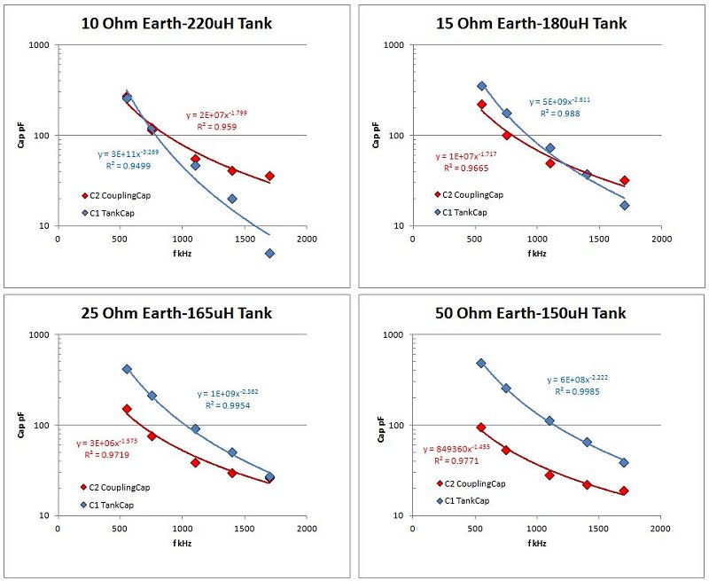
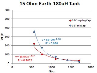
The above plots show the calculated capacitance versus frequency for four different models of Earth Resistivity / Tank Inductance. In each case I maintain the same log capacitance vs frequency scale for easy comparison. The cases modeled represent increasing earth resistance presented to the ATU from a very low 10 ohms to a fairly high 50 ohms. Actual earths can go up to two orders of magnitude higher. I chose L1 inductances such that the maximum needed capacitance would approach 500pFs, easily found on many variable caps. With respect to the coupling cap (C2, red curve), as the earth resistivity increases, the needed capacitance declines. The tank cap value needs to resonate with the inductor and increases with smaller-value inductance. In searching for a 500pF cap max value, the choice of inductance needs to decrease with increasing earth resistance. Parameters other than Rg, L1 and C1-C2 have minor impact on the models.
Conclusions:
From the plots one can readily see that above 15 ohm earth the two variable capacitors on the ATU do not track well. As the earth resistivity increases, the worse the tracking. Most locations are not blessed with a low resistivity earth and this needs to be factored into the ATU design. There is little to be done, changing the design coil inductance will change the needed capacitance on BOTH C1 and C2, (larger L1 leads to smaller C1 and C2 for resonance and vice versa). A possible solution well worth trying is to use a dual-gang capacitor where one section has a different value than the other, the above plots give an easy way to decide the max values needed. Use the smaller gang on the coupling circuit and the larger on the tank. Experience tells us that ganging the capacitors on a "Tuggle" front end works well, but from the models I have to imagine one might squeeze a bit more performance by giving up the convenience of one-dial tuning on the ATU, especially where your earth has a fairly high resistance.
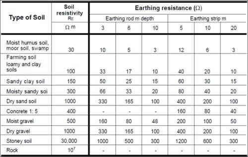
The best design methodology requires that you know first and critically your earth resistance. If this is just a guessed-at parameter then I strongly urge you to put down the Litz, set aside the silver-plated-ceramic-insulated caps, box the holy-grail diodes and go do some research on your local ground. All the time, expense, and effort on the greatest "state-of-the-art" crystal receiver will be wasted if the ground is not attended to. If the resistivity of your earth is high in ohm-meters, get more metal in the ground or consider a counter-poise. The following table from LEM Instruments shows the relation between earth resistivity in ohm meters and actual earth resistance in ohms as a function of the earthing method used.
Given just how little discussion there is on the web concerning antenna tuning and the impact of ground resistivity I hope this page can serve as a starting point for further research. Certainly there is more to be said, Crystal Radio, its a bottomless pit!
Kevin Smith
09/2011
Models and Data:
10 ohm / 220 uH  Lowest resistivity Earth Case sensitivities
Ra	Ca	La	L5	Qu	f	C4 cpl	C6 tank	Za Impedance	LC Rp
Ohm	pF	uH	uH		kHz	pF	pF	     Ohm	kOhm
10	220	20	220	475	550	442	228	10  -j  1246	361
10	300	20	220	400	1100	68	36	10  -j  344	608
10	375	20	220	200	1700	44	-3	10  -j  36	470

10	220	20	220	700	550	273	255	10  -j  1246	532
10	260	20	220	640	750	114	122	10  -j  721	663
10	300	20	220	585	1100	55	47	10  -j  344	890
10	340	20	220	440	1400	41	20	10  -j  158	851
10	375	20	220	300	1700	36	5	10  -j  36	705

10	220	20	200	700	550	304	287	10  -j  1246	484
10	300	20	200	585	1100	58	54	10  -j  344	807
10	375	20	200	300	1700	38	7	10  -j  36	641


15 ohm / 180 uH  Low resistivity Earth Case sensitivities
Ra	Ca	La	L5	Qu	f	C4 cpl	C6 tank	Za Impedance	LC Rp
Ohm	pF	uH	uH		kHz	pF	pF	     Ohm	kOhm
15	220	20	180	475	550	337	328	15  -j  1246	295
15	300	20	180	400	1100	61	63	15  -j  344	498
15	375	20	180	200	1700	40	10	15  -j  36	385

15	220	20	180	700	550	220	352	15  -j  1246	435
15	260	20	180	640	750	100	176	15  -j  721	543
15	300	20	180	585	1100	49	73	15  -j  344	728
15	340	20	180	440	1400	37	37	15  -j  158	697
15	375	20	180	300	1700	32	17	15  -j  36	577

15	220	20	130	700	550	313	511	15  -j  1246	314
15	300	20	130	585	1100	59	110	15  -j  344	526
15	375	20	130	300	1700	38	30	15  -j  36	417

15	220	20	205	700	550	195	302	15  -j  1246	496
15	300	20	205	585	1100	45	61	15  -j  344	829
15	375	20	205	300	1700	30	13	15  -j  36	657


25 ohm / 165 uH  "Standard" resistivity Earth Case sensitivities
Ra	Ca	La	L5	Qu	f	C4 cpl	C6 tank	Za Impedance	LC Rp
Ohm	pF	uH	uH		kHz	pF	pF	     Ohm	kOhm
25	220	20	165	475	550	213	396	25  -j  1246	271
25	300	20	165	400	1100	48	84	25  -j  344	456
25	375	20	165	200	1700	32	22	25  -j  36	352

25	220	20	150	700	550	164	462	25  -j  1246	363
25	300	20	150	585	1100	41	102	25  -j  344	606
25	375	20	150	300	1700	27	31	25  -j  36	481

25	220	20	165	700	550	151	416	25  -j  1246	399
25	260	20	165	640	750	76	213	25  -j  721	498
25	300	20	165	585	1100	39	91	25  -j  344	667
25	340	20	165	440	1400	30	50	25  -j  158	639
25	375	20	165	300	1700	26	27	25  -j  36	529

25	220	20	200	700	550	130	335	25  -j  1246	484
25	300	20	200	585	1100	35	72	25  -j  344	807
25	375	20	200	300	1700	24	20	25  -j  36	641


50 ohm / 150 uH  High resistivity Earth Case sensitivities
Ra	Ca	La	L5	Qu	f	C4 cpl	C6 tank	Za Impedance	LC Rp
Ohm	pF	uH	uH		kHz	pF	pF	     Ohm	kOhm
50	220	20	150	475	550	128	476	50  -j  1246	246
50	300	20	150	400	1100	34	108	50  -j  344	415
50	375	20	150	200	1700	24	35	50  -j  36	320

50	220	20	150	700	550	96	490	50  -j  1246	363
50	260	20	150	640	750	53	256	50  -j  721	452
50	300	20	150	585	1100	28	113	50  -j  344	606
50	340	20	150	440	1400	22	65	50  -j  158	581
50	375	20	150	300	1700	19	39	50  -j  36	481

50	220	20	125	700	550	110	595	50  -j  1246	302
50	300	20	125	585	1100	31	139	50  -j  344	505
50	375	20	125	300	1700	21	49	50  -j  36	401