I set about my study by gathering what I could find on the web concerning capacitor Q. The result was, not a whole lot, at least not for air-variable capacitors. The exception comes from Ben Tongue (not surprisingly) and I wish to extend special thanks to him for providing, as usual, essential measurements and background in his Article 24. The plots below show capacitor Q versus capacitance, and versus frequency for a small number of air-variable capacitors that I have in the box. Note that I made all my measurements with a calibrated inductor coil (236 uH at 1 Mhz) so the capacitance and frequency are related to each other by the resonance equation: f = 1 / 2pi sqrt(LC).
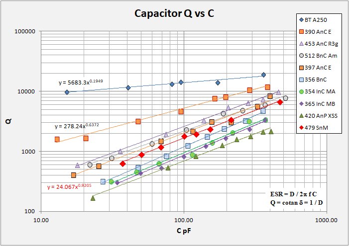
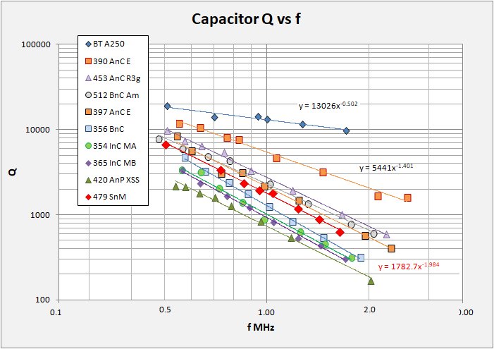
These are simple plots with log Q versus log capacitance in pF and versus log frequency in MHz. On each plot, a bit messy I admit, I show data for eight capacitors along with the Q versus f equation. You immediately see that for each capacitor the relation follows a power function and in all cases the function is good to R-squared at or above 99%. Additionally, I include the same data for two capacitors presented in Ben Tongue's excellent summary. It is also immediately obvious that not all caps are created equal!
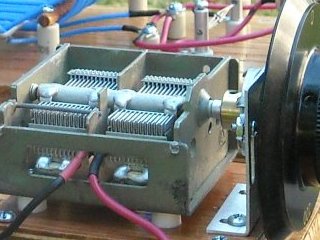
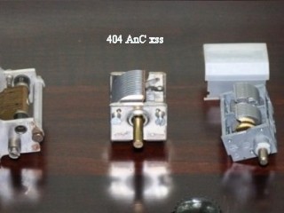
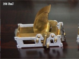
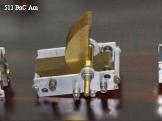
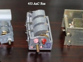
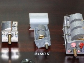
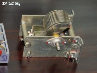
I have named the caps in the following manner, the highest tested RF capacitance, materials of interest (A = aluminum plates, B = brass plates; C = ceramic insulators, P = phenolic insulators); finally something to do with the origin. Photos of the caps at the bottom of this page.
Identification of the caps as follows (from highest to lowest Q):
BT CapA		Ben Tongue's CapA is the best "Holy Grail" of the lot
383 AnC E	A Russian (I presume) eBay cap from Estonia
453 AnC Rus	A Russian cap frequently offered on eBay
512 BnC Am	A brass straignt-line frequency cap AMSOO
397 AnC E	Another Russian (I presume) eBay cap from Estonia, larger capacitance
356 BnC		Another Lovely straight-line frequency brass cap
354 InC M	Chinese caps (A and B) offered from Ming on eBay
404 AnC xss	A typical Crystal Set Society cap
479 SnM		Switched set of individual Silver Mica caps, not an air-variable
The following table summarizes the Q versus Capacitance (in pF) for each tested cap, arranged from highest to lowest quality.
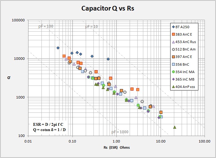
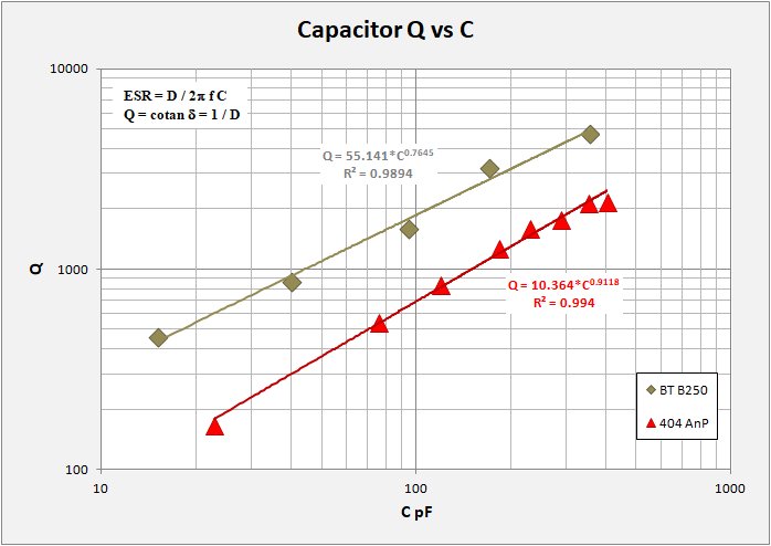
Cap		Q vs C in pF		R2
BT A250		Q = 5683.3* C^0.1949	0.9340
390 AnC E	Q = 278.24* C^0.6372	0.7950
453 AnC Rus	Q = 45.665* C^0.8775	0.9968
512 BnC Am	Q = 47.095* C^0.8326	0.9928
397 AnC E	Q = 31.498* C^0.903	0.9867
356 BnC		Q = 9.6513* C^1.0455	0.9986
403 AnC EB	Q = 7.4831* C^1.0957	0.9949
337 AnC EB	Q = 6.6011* C^1.1043	0.9791
383 AnC EA	Q = 8.9089* C^1.0323	0.9921
354 InC MA	Q = 9.9566* C^0.9891	0.9859
365 InC MB	Q = 8.5243* C^1.0028	0.9953
404 AnP xss	Q = 10.364* C^0.9118	0.9940
Any discussion of component quality needs first to acknowledge that the fight to increase the component Q is in reality a fight to eliminate (not possible) or reduce as much as feasible the resistive losses associated with that component. It helps then to look not just at Q, but at how Q relates to the component series resistance Rs or ESR. There are two fundamental equations that describe this relation: 1) Q = cotan theta = 1/D. D is the dissipation factor and is an attribute of the dielectric material used in the construction of the capacitor. D = tan theta = ESR / Xc = 2pi f C * ESR. Solving for ESR we get: 2) ESR = D / 2pi f C. This equation tells us that capacitor losses expected due to resistance are dependant on both angular frequency and capacitance. It is important to remember that not all Q's are created equal. What we want is to keep the ESR to a minimum.
The plot below summarizes the same data only this time plotting log Q versus log Rs (ESR). Here most of the data sets fall into a narrow zone running from High-Q / low ESR in the upper left to Low-Q / high ESR in the lower right. Ben Tongue's Holy Grail cap sits above the pack with an overall narrower range of ESR from max to min capacitance. No surprises, good caps are low-loss. I have also plotted lines of Q versus ESR at 1MHz for threee capacitance values, 10, 100, and 1000 pF. These lines indicate that Q is highest at high values of capacitance independant of individual capacitor loss. Note that all the caps measured straddle the 100 pF line. For typical MW coils with about 230 uH or so, 100 pF resonates around 1MHz.
From the datasets above it can be seen that high-Q caps are high-Q across the band, but Q varies and is highest at high capacitance, (lower frequency) and vice versa. All sets show a direct power-law relation between Q and f or ESR regardless of overall quality or type of capacitor. The data table from Ben Tongue (below) was found in his Article 24 and represent precision measuremnts by Bill Hebbert.
     pF	  	f	      Q
cap	tank	MHz	Cap A	Cap B
355	375	 520	19000	4750
170	190	 730	14000	3230
 94	114	 943	14400	1610
 81	101	1000	13148	1828	(my estimate)
 40	 60	1300	11600	 870
 15	 35	1710	 9800	 460

for I = 250 uH and 20pF stray in tank
Some notes on my results. It should be immediately clear that I have yet to snag an actual "holy grail" cap such as the one evaluated by Ben Tongue. Ben's good CapA has ceramic insulated stators and silver-plated brass plates with silver-plated wiper contacts. Essential features of a good cap. Inexpensive caps often have lossy phenolic insulators, something easily noticeable before you buy, look for this. I have noticed that on some caps the stator is held by ceramic "buttons" rather than a large ceramic plate and I have to wonder how effective this is. I would say that ceramic insulation is far more available that silver plating on the plates and wipers. At the bottom end of the quality profile is the poor but readily available XSS variable cap (404 AnP). This has aluminum plates, phenolic insulation and a single aluminum wiper. An OK basic cap, but one easily beat if you are willing to make an effort. Next up in terms of quality was a big disappointment for me. These are two Chinese caps I recently purchased on eBay (354 and 365 InC). They are large and heavy units with big ceramic insulators and I figured this ought to be good. Both caps have decidedly lower Q that my vintage brass straight-line frequency caps. I do not think these will find their way into any radios here.
In the mid-Q range I find one brass cap (512 BnC) and two Russian caps (453 AnC, and 397 AnC). These all have ceramic insulation but no silver plating. The brass cap insulators are a black material that I call ceramic as it does not appear phenolic, but frankly I am unsure what it is. The cap is pretty good though. The two Russian caps are commonly available on eBay and are of two different styles. One somewhat large with thick "gun metal" type casing and the other a small delicate unit with a plastic dust-cover. Both are pretty good caps.
Finally and best cap that I have in my box is another Russian cap (383 AnC). This cap is clearly an unused NOS unit with clean shiny parts and button ceramic insulators. This is a slightly smaller version of one of the previous caps (397 AnC). The moderate Q version was also clean and NOS, so I do not expect all such caps to be automatically good Q. It is a pity as I have seen additional of these small caps on eBay, though clearly in used condition so I suspect they will have lower Q.
From all the above I would conclude that caps having ceramic insulation alone is not nirvana. Caps need also to be clean and ultimately need silver plating to truly aspire to "holy grail" status. A good reference worth looking at is a thread on The Radio Board:
Improving 'Q' of capacitors.
The post shows how merely taking an older cap and cleaning it up (no small task) and replacing the insulators with HDPE sheet (high-density polyethylene) can take an original Q = 664 (1MHz) and raise it to Q = 12248 (1MHz). This value is on par with Ben Tongue's "holy grail" cap (Q = 13148 @ 1MHz) and either it was a dim fine cap to start with or something not fully kosher with the measurements. Still, the point is that improvements can be significant.
Note: A summary look at the cap Q taken (calculated) at 1 MHz
383 AnC E	5441 Q @ 1Mhz
512 BnC Am	2995
453 AnC Rus	2742
397 AnC E	2132
356 BnC		1280
383 AnC EA	1102
403 AnC EB	1245
337 AnC EB	1149
354 InC M	1015
479 SnM		1177
404 AnP xss	 733
498 AnC a	 622
498 AnC b	 487
A word of caution, that really great Estonia cap with the high Q seems kinda unique. I measured two additional similar caps (383 AnC EA, and 403/337 AnC EB (two gangs)) thinking I would get similar great results. What I got in fact were two mediocre results. If you plan to run out and buy these type of cap on ebay, don�t say I didn't warn you!
kjs (updated 6/2016)
Ben Tongue 1999, Sensitivity and selectivity issues in crystal radio sets including diode problems; measurements of the Q of variable and fixed capacitors, RF loss in slide switches and loss tangent of various dielectrics.
http://www.bentongue.com/xtalset/24Cmnts/24Cmnts.html
Wikipedia, Types of Capacitors, Ohmic Losses, Dissipation Factor and Q.
http://en.wikipedia.org/wiki/Types_of_capacitor#Ohmic_losses.2C_ESR.2C_dissipation_factor.2C_and_quality_factor
Dr. Gary L. Johnson, 2001. Lossy Capacitors
http://www.eece.ksu.edu/~gjohnson/tcchap3.pdf

A short note concerning my Q measurements as compared to those of Bill Hebbert and presented by Ben Tongue in his Article 24. By some chance, both Ben's work as well as my own include a commonly available 365 pF capacitor from the XSS and elsewhere. While his cap and my own are not the same unit, their properties ought to be similar enough. Therefore it is worth to take a look ar the two datasets together.
In the plot below of Q vs Capacitance I show Ben's three measurement sets as well as my own measuremnts on the same type cap. His measurements on CapB were made with two separate inductors, one with 250 uH and one with 180 uH. My standard inductor has 225 uH, so here I compare my 225uH data with Ben's 250 uH data. On the plot I show dark green markers for Ben's 250 uH (BT B250) dataset and red markers for my 225 uH (404 AnP) data. It is clear that my Q measurements are systematically lower than his.
At this time I am uncertain as to whether my setup delivers lower Q measurements or if the partictular cap I measured was a bit more lossy than Ben's. This is a bit of ambiguity in my presentation that the reader ought to be aware of. Maybe my caps are better than presented? I do not know the answer but I include this plot just so you know.
A note concerning Loss Tangent
When looking into capacitor losses one often runs into the term "loss tangent". For many our eyes just glaze over and we read on understanding only that it has something interesting to do with theory. In the interest of knowing the code I give a brief explanation.
With a perfect lossless capacitor in AC operation (sine wave) current leads the voltage by 90 degrees. Where losses occur the current will lead by slightly less than this. If you imagine these losses as a resistance in series with a perfect capacitor, then this is called Effective Series Resistance, ESR and is valid in reference to a specific frequency: ESR = D / 2pi * f * C.
The lag angle between current and voltage is generally a fraction of a degree and is expressed as a positive value. The tangent of this lag angle is the "loss tangent" and is referred to more commonly as the Dissipation factor D. For example, polystyrene has a D of about 0.0001 for a lag angle of 0.006 degrees. Good dielectrics have very small loss tangents. Why do we express loss as D or loss tangent? Well, it related to the quality factor Q such that Q = 1/D.
Modeled Data from plots shown above:
f L C Qtank Qcoil Qcap Rp ESR D Qvsf R� MHz uH pF Mohm ohm Brass n Ceramic 356 BnC Q = 1280.1 * f^-2.271 0.9991 1.878 267 27 142 258 315 0.99 10.03 0.003179 1.461 252 47 174 256 541 1.25 4.27 0.001849 1.183 241 75 190 245 835 1.50 2.14 0.001197 1.013 234 105 198 235 1240 1.85 1.20 0.000806 0.875 229 144 199 225 1735 2.19 0.726 0.000576 0.769 225 190 198 216 2358 2.56 0.461 0.000424 0.655 221 268 192 205 3238 2.94 0.280 0.000309 0.572 217 356 188 196 4713 3.69 0.166 0.000212 Aluminum n Ceramic Estonia A 383 AnC E Q = 5441 * f^-1.401 0.9901 2.587 295 13 196 223 1609 7.70 2.98 0.000622 2.116 277 20 218 251 1671 6.15 2.20 0.000598 1.460 251 47 237 256 3197 7.38 0.72 0.000313 1.066 236 94 227 238 4676 7.40 0.34 0.000214 0.827 227 163 215 221 7701 9.09 0.153 0.000130 0.761 225 195 209 215 8135 8.74 0.132 0.000123 0.636 220 285 199 203 10574 9.29 0.083 0.000095 0.552 217 383 190 194 11912 8.96 0.063 0.000084 Aluminum n Phenolic XSS 404 AnP xss Q = 732.75 * f^-1.98 0.9922 2.019 273 23 101 255 169 0.58 20.52 0.005929 1.176 241 76 169 245 547 0.97 3.25 0.001827 0.957 232 119 181 231 845 1.18 1.65 0.001184 0.783 226 183 186 217 1286 1.43 0.86 0.000778 0.703 222 230 185 209 1604 1.58 0.613 0.000624 0.632 220 288 182 202 1790 1.56 0.488 0.000559 0.573 218 354 180 196 2149 1.68 0.365 0.000465 0.539 216 404 176 192 2185 1.60 0.335 0.000458 Aluminum n Ceramic Russia 3-gang 453 AnC Rus Q = 2742 * f^-1.911 0.9966 2.248 282 18 173 245 588 2.34 6.76 0.001699 1.661 259 35 206 259 1007 2.72 2.69 0.000993 1.191 241 74 218 246 1933 3.49 0.93 0.000517 0.899 230 136 212 227 3329 4.33 0.39 0.000300 0.748 224 202 206 214 5435 5.73 0.194 0.000184 0.642 220 279 197 203 6451 5.73 0.138 0.000155 0.574 218 354 191 196 7358 5.77 0.107 0.000136 0.510 215 453 185 189 9783 6.74 0.070 0.000102 Brass n Ceramic Amsoo 512 BnC Am Q = 2294.7 * f^-1.806 0.9915 2.057 274 22 179 253 607 2.15 5.84 0.001647 1.763 263 31 195 259 787 2.29 3.70 0.001270 1.318 246 59 212 251 1356 2.76 1.50 0.000737 1.021 235 104 214 236 2332 3.51 0.65 0.000429 0.776 225 187 206 216 4371 4.80 0.251 0.000229 0.669 221 255 198 206 4866 4.53 0.191 0.000206 0.564 217 367 189 195 6005 4.62 0.128 0.000167 0.481 214 512 181 185 7834 5.07 0.083 0.000128 High-stability Invar n Ceramic Ming A 354 InC MA Q = 1014.5 * f^-2.145 0.9871 21.769 263 31 142 259 315 0.92 9.29 0.003173 1.475 252 46 164 256 455 1.06 5.14 0.002199 1.252 244 66 178 248 631 1.21 3.04 0.001585 0.980 233 113 184 233 880 1.26 1.63 0.001136 0.845 228 156 192 222 1389 1.68 0.871 0.000720 0.724 223 216 192 211 2050 2.08 0.496 0.000488 0.637 220 284 190 203 3161 2.78 0.278 0.000316 0.562 217 369 184 195 3351 2.57 0.229 0.000298 Aluminum n Ceramic Estonia B 397 AnC E Q = 2132 * f^-1.976 0.9875 2.313 284 17 152 242 411 1.70 10.06 0.002436 1.940 270 25 177 257 573 1.88 5.74 0.001745 1.239 243 68 213 248 1499 2.84 1.26 0.000667 0.978 233 114 210 233 2168 3.10 0.66 0.000461 0.847 228 155 208 222 3125 3.79 0.388 0.000320 0.733 224 211 199 212 3105 3.20 0.332 0.000322 0.598 218 324 192 199 5687 4.67 0.144 0.000176 0.543 216 397 188 193 8446 6.24 0.087 0.000118 High-stability Invar n Ceramic Ming B 365 InC MB Q = 927.01 * f^-2.170 0.9960 1.697 261 34 140 259 306 0.85 9.08 0.003269 1.434 250 49 162 255 441 0.99 5.12 0.002270 1.231 243 69 169 247 535 1.01 3.51 0.001868 1.045 236 98 184 237 824 1.28 1.88 0.001213 0.887 230 140 191 226 1244 1.59 1.029 0.000804 0.762 225 194 191 215 1685 1.81 0.639 0.000594 0.636 220 284 186 203 2338 2.06 0.376 0.000428 0.565 217 365 184 195 3386 2.61 0.228 0.000295 Aluminum n Ceramic Estonia 383 AnC EA Q = 1102.1 * f^-2.266 0.9938 0.558 217 375 186 194 4652 3.54 0.16 0.000215 0.608 219 313 189 200 3382 2.83 0.25 0.000296 0.714 223 223 194 210 2472 2.47 0.40 0.000404 0.879 229 143 190 225 1240 1.57 1.02 0.000807 1.032 235 101 191 236 988 1.51 1.543 0.001012 1.256 244 66 181 249 666 1.28 2.887 0.001502 1.976 271 24 118 256 220 0.74 15.338 0.004554 2.469 290 14 95 232 160 0.72 28.201 0.006268 Aluminum n Ceramic Estonia 403 AnC EB Q = 1245 * f ^-2.405 0.9962 2.490 291 14 85 230 135 0.61 33.69 0.007404 2.136 277 20 118 251 223 0.83 16.65 0.004474 1.734 262 32 148 259 346 0.99 8.24 0.002887 1.314 246 60 177 251 605 1.23 3.35 0.001652 1.012 234 106 193 235 1078 1.61 1.383 0.000928 0.848 228 154 197 222 1716 2.08 0.708 0.000583 0.624 219 297 192 201 3979 3.42 0.216 0.000251 0.549 217 388 187 193 5828 4.36 0.128 0.000172 Aluminum n Ceramic Estonia 337 AnC EB Q = 1149 * f ^-2.429 0.9810 2.395 287 15 94 237 156 0.68 27.62 0.006390 2.039 274 22 111 254 197 0.69 17.83 0.005084 1.525 254 43 155 257 390 0.95 6.24 0.002565 1.200 242 73 184 246 730 1.33 2.49 0.001369 1.013 234 105 190 235 1005 1.50 1.484 0.000995 0.865 229 148 198 224 1742 2.16 0.714 0.000574 0.703 222 231 190 209 2052 2.02 0.479 0.000487 0.598 218 325 191 199 5355 4.39 0.153 0.000187