
I have been building and studying crystal radios for some time now and slowly begin to learn a few things about these marvelous sets. In this section I begin my exploration of coil, coil quality and that mysterious dimensionless factor, Q... I start by presenting data on coil Q turfed up from web, with many thanks to those who publish their data! Secondly I present my own Q measurements on four "typical" coils I have laying about. Lastly I play with some Litz wire resistance calculations, just for the pleasure.
My purpose here is to present some facts and data that resulted from my explorations of the web. I have often wondered at what the quality factor of my coils should be and as often realized that I really do not have any expectations as to what is possible. Now, having done some research, I can with some confidence say that this is solved. Coils as used in crystal radio broadcast band reception typically employ coils with Q factors ranging from 100+ (pretty lousy) through the several 100's (decent) and on up to 1000 or more for those remarkable Big-Litz wonders ($$$). Knowing the expected (or actual) Q of your coil is important in so far as it impacts the choice of diode to be used in the set. On my page of Diode Calibration I present a summary graphic which indicates how the diode Rd value relates to the tank parallel resistance Rp. This Rp in turn is a function of the coil Q. Schezzam! So here we are.
In your set construction, with a good effort and good engineering practice one can easily expect to wind a solenoid coil in the Q = 200 range without much trouble, even with a cardboard form, sealed, of course. With various "open" coils, spiderweb, basket weave, diamond weave, etc. you may expect to double that.. possibly. The advantage in open coils derives from first the separation between adjacent wire turns which reduces self-capacitance in the coil, and secondly from the obvious lack of a form. All materials used in the coil will have some amount of dielectric losses associated with them and the less material used the better. Air core coils are best in this respect. I am not here to speak about ferrite coils as I have no experience with them. Frankly, they seem (to me) a bit like cheating.
The following graph presents data that I have scoured off the web. My primary sources include Hund and Groot, 1925*, Wes Hayward, Dave Schmarder, Ken Khun, Mike Tuggle, Steve Ratzlaff, and Dick Kleijer. 10,000 thanks for those who post their data on the web! This plot gives the Q value as a function of coil Rp (parallel resistance). In striving for a high Q coil, in effect one is eliminating losses and increasing parallel resistance (lowering series resistance) as much as possible. There is more to it of course. The Q formulas Qu = Rp / 2pifL and Qu = 2pifL / Rs tells us that Q is a function of the coil inductance L and the frequency f of the measurement as well as resistance.
All measurements chosen for plotting are made around 1 Mhz and most of the coils are in the L = 200 - 350 uH range. So, despite the formulas, in this plot the coil Rp is the main driver. From either plot it should be apparent that winding a coil with Q = 200 or better should be a no-brainer. If your coil Q is less, you just aren't trying. Most coils I have found to be in the Qu = 150 - 500 range. At the high end, Q's > 1000 seem to be pretty extreme and these coils are expensive. You better be using big Litz 660/46 and use a basket design (although the two best coils on the plot were solenoids, go figure!).
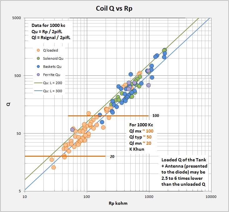
For this plot, green, blue, and purple circles are for published unloaded coil Q. I also post in orange circles an estimate of what the loaded Q presented to the diode (Antenna + Tank) might look like. Loaded Q will always be lower than the unloaded Q by several times. I have estimated that high-end sets (big litz, silver-plated ceramic insulated caps, best wiring practices) may lower the Q by about 2 1/2 times (B Tongue's performance set has Q = 700). At the low end (vintage components, small solid wire coils, taps) the load may lower Q by up to 6 times. Ken Khun in his excellent web book states that typical sets at 1Mhz have a loaded Q between 20 and 100, 50 typical and this is where most of my own data falls with the assumptions previously stated. I scaled the divisor by Qu to produce the above plot but note that this is merely an estimate. Having an idea of your set's Ql will allow a better selection of the proper diode for matching.
All the previous data was from published sources and all are for coil Q measurements made at or near 1MHz. It is interesting to look at how Q varies across the tuning range of the coil as well. Having had a chance to make a few Q measurements myself recently (Q2 2016) I finally have results to show and discuss, results across the broadcast band. The following data and plots result from the technique presented in the section "Coil Q Revisited". Calibrations for my measurements are based on capacitor Q measurements made on my behalf by Steve Ratzlaff AA7U with his HP Q-meter. It is worth to note that my capacitor used in these measurements has a low end capacitance of 8 pF, 18 pF and radio frequency. This allows measurements out to nearly 2.3 MHz.
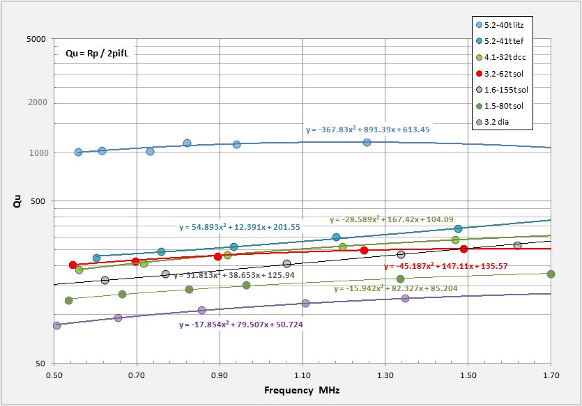
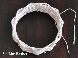
The above plot gives unloaded coil Q versus frequency for a set of several crystal set coils I have wound (or purchased in
the case of the diamond weave). I have chosen coils with what I had hoped to have a variety of performances, from a big
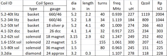
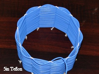
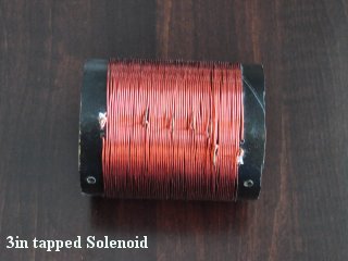
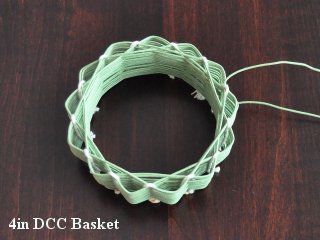
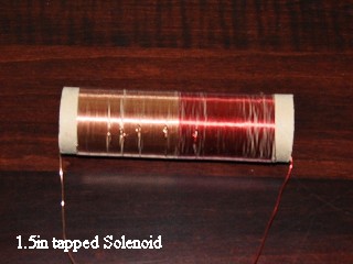
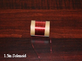
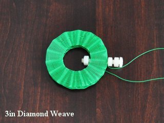
litz rope basket coil to a close wound tapped solenoid on cardboard stock from. I even threw in a couple small-gauge tp-form coils just to see how bad things can get (to offset the Litz as it were). The set includes the following coil
specs (note, coil photos at end of this section):
On the plot itself I post the measured data points and add a best-fit regression and formula describing the relation for each coil. Note that in most cases the regressions have fits with 0.99 or above except the litz coil with 0.88 and the 3.2" tapped solenoid with 0.98. Additionally I have added in grey a few lines of equal parallel resistance (for L=220 uH). These allow a visualization of how the coil Q relates to Rp according to the function Qu = Rp / 2pifL.
The graph clearly shows the litz coil with superior performance, the solenoid and DCC basket coils have similar moderate-low performance and the poor diamond-weave coil lies at the bottom. For the litz coil (light blue dots) and solenoid coil (red dots) we see a good curve with Q peaking in the middle of the band. With the silver-plated teflon insulated coil I originally had very high hopes. This wire does perform above average, but for its high price one would do well just to use big Litz. The diamond weave coil (purple dots) appears to be peaking near the top of the band. The curve for the DCC basket is interesting in that its Q peaks near the top of the band. The wire for this coil I bought on ebay and was disappointed when it arrived. While it has an absolutely beautiful green covering, the wire itself is small gauge, about 26awg and worse appeared to be plated. At first I assumed the plating was tin to protect the wire from corrosion. Because of skin effect the current in the wire concentrated on the outer wire surface at radio frequency. Therefore a plating can increase the resistance and losses. I find from my measurements that this wire in fact performs quite well and am currently assuming the plating is silver.
The general vision of a BCB coil with unloaded Q peaking in the middle of the band is instructive. Again I remind that the published data I have presented in the first part above is for 1MHz, near the "typical" peak Q. The coil Q's will certainly drop in the lower frequencies and possibly in the high as well.
Now a look at the coil Rp
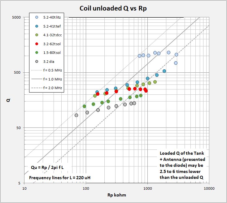
For a look at Rp I turn again to my favorite Q versus Rp plot. Tank Rp is the essential parameter one wishes to know for the purpose of matching tank to diode and load. Plot display and colors are as before and I have included some lines of constant frequency for the case of L = 220 uH, a pretty normal coil. This plot illustrates that, for any single coil, Rp is not constant across the entire broadcast band although at higher frequencies (above 2 MHz) some coils have a tendancy towards constant Rp. No single diode will be matched across the band for a single coil and Rp differences between different coils can be dramatic. Diode matching MUST be coil-specific. It seems good practice to choose your diode for a partictular coil at about f = 1MHz. Note that in this plot I give unloaded coil Q. When you load the coil with the capacitor, diode, antenna, and audio the Q (and therefore Rp) will drop somewhere between 2.5 to 6 times. I have attempted to illustrate this in my first "Coil Q vs Rp" plot at the beginning of the page.
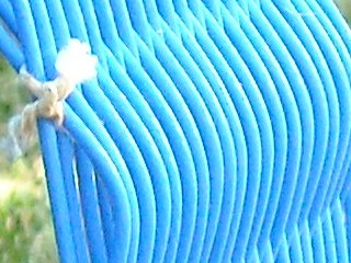
Images of the tested coils, same scale.
A Calculation of 660-46 wire resistance in a high-end coil:
As much of the resistive loss is in the coil, keeping this to a minimum is important. The following discussion provides
a few calculations on Litz wire AC resistance. NOTE: THE ULTIMATE LIMIT ON COIL Q IS THE NEED TO USE WIRE!
From different Litz wire manufacturing sites one can find tables and data allowing the calculation of the resistance of
your favorite litz wire.
The formula for the D.C. resistance of any Litz construction is:
Rdc = Rs (1.0515)^Nb * (1.025)^Nc / Ns
Where:
Rdc = Resistance in Ohms/1000 ft.
Rs = Maximum D.C. resistance of the individual strands (4544 for 46awg wire)
Nb = Number of Bunching operations (assume = 2)
Nc = Number of Cabling operations (assume = 1)
Ns = Number of individual strands (assume = 660)
Rdc = 4544 (1.015)^2 (1.025)^1 / 660 = 7.27 ohms / 1000 ft.
The ratio of AC resistance to DC resistance of any Litz construction is:
Rac/Rdc = S + K (N Di / Do)^2 * G
Where:
S = Resistance ratio of individual strands when isolated (1.0003 for 46awg wire)
G = Eddy Current basis factor = (Di * sqrt(f) / 10.44)^4
F = Operating Frequency in HZ (assume 1MHz)
N = Number of strands in the cable = 660
Di = Diameter of the individual strands over the copper in inches = 0.0016
Do = Diameter of the finished cable over the strands in inches = 0.056
K = Constant depending on the number of strands = 2
Rac/Rdc = 1.0003 +2(660*0.0016 / 0.056)^2 * (0.0016*1000 / 10.44)^4 = 1.393
Therefore the AC Resistance of 660/46 litz wire is approximately :
The A.C. resistance is: 1.39 * 7.27 = 10.13 ohms/1000ft.
An example in real life:
For 53ft of Litz wire to wind a coil:
Rac = 53 * 10.13 ohm/1000ft
Rac = 0.54 ohms
For Qu = 2pifL / Rs
at 1 MHz and L = 230 uH
Qu = 2pi * 1 * 230 / 0.54ohms
Qu = 2692
A 5inch diameter basket weave coil made from 660/46 Litz wire having an inductance of 230 uH will typically require some 40 turns or about 53ft of wire. At 10.13 Ohm/kft, that comes to an AC wire resistance of 0.53 ohms for the coil alone. Were all the losses represented by series resistance of the wire, the coil would have, at 1 MHz an unloaded Q = 2700! This is as good as things can get. Naturally, wire resistance is not the only source of loss in the tank. There is a capacitor, metallic objects intruding into the magnetic field of the coil, dielectric losses, eddy current and other losses. Its no wonder that the best coils just top out just above Q = 1000 or so.
Time to get measuring. Below I provide my input data, have at it!
Kevin Smith
03/2013
*Note that in 1925 the importance of coil Rs was understood, but the factor Q was apparently not used. I have taken
(quite painfully) the L and Rs data from the Hund and Groot plots and calculated the resulting Q. I recommend to those interested to download the pdf of their paper.
https://archive.org/details/radiofrequency1925298hund
Modeled Data:
Radio-Frequency Resistance and Inductance of Coils used in Broadcast Reception:
Series:		Qu = 2pifL / Rs
Parallel:	Qu = Rp / 2pifL
									     1000 Khz
Coil Type	Wire		Core		Dia	Length	turns	Rs	Rp	L	Q		Source
		awg	type			in	in		ohm	Mohm	uH
solenoid	660/46	litz	styrene				36	0.90	1.76	200	1400		Ratzlaff
solenoid	660/46	litz	styrene		4.50	3.00	44	0.91	1.73	200	1375		Hayward
solenoid	175/46	litz	air		5.00			2.88	0.96	265	579		Hayward
solenoid	12	vinal	plastic?	7.15			2.98	0.70	230	485		Kuhn
solenoid	14	vinal	plastic?	6.25			3.28	0.64	230	440		Kuhn
solenoid	16	mgnt	plastic?	3.45	3.18	57	3.52	0.59	230	410		Kuhn
solenoid	18	mgnt	plastic?	2.90	2.90	71	4.01	0.52	230	360		Kuhn
solenoid	50/46	litz	space wound	4.20	2.90		4.89	0.61	275	353		Hayward
solenoid	32/38	litz	hard rubber	3.31	2.41	65	6.20	0.68	327	331		Hund
solenoid	20	mgnt	plastic?	2.50	2.50	77	4.66	0.45	230	310		Kuhn
solenoid	16	dcc	hard rubber	6.65	2.73	40	7.60	0.53	319	264		Hund
solenoid	28	dcc	Varnish A	3.31	1.29	55	8.80	0.58	360	257		Hund
solenoid	22	mgnt	plastic?	2.10	2.76	88	5.78	0.36	230	250		Kuhn
solenoid	24	dcc	hard rubber	3.35	1.84	60	8.10	0.50	319	247		Hund
solenoid	28	dcc	Schellac	3.31	1.29	55	10.10	0.51	360	224		Hund
solenoid	28	dcc	Paraffin	3.31	1.29	55	10.30	0.50	360	220		Hund
solenoid	50/46	litz	close wound	4.20	1.52	53.25	10.84	0.52	378	219		Hayward
solenoid	24	mgnt	plastic?	1.80	2.29	94	6.72	0.31	230	215		Kuhn
solenoid	28	dcc	Varnish B	3.31	1.29	55	9.60	0.44	327	214		Hund
solenoid	28	dcc	hard rubber	3.31	1.29	55	9.70	0.41	319	207		Hund
solenoid	26	mgnt	plastic?	1.55	2.00	102	8.03	0.26	230	180		Kuhn
solenoid	18	magnet	cardboard	3.5	2.90		7.94	0.29	240	189		smith
solenoid	22	magnet	cardboard	1.5	4.30		8.67	0.32	265	192		smith
solenoid	30	magnet	cardboard	1.5	0.96		9.44	0.24	242	161		smith
solenoid	28	dcc	Spar Varnish	3.31	1.29	55			327			Hund

basket weave	660/46	litz	air		5.00	1.94	51	1.03	1.33	186	1134		Tuggle
basket weave	660/46	litz	air		5.00	2.25	42	1.08	1.26	186	1082		Tuggle
basket weave	660/46	litz	air		5.2	2.0	40	0.96	1.46	227	1591		smith
basket weave	660/46	litz	air		5.2	2.5	46	1.39	1.58	273	1169		smith
spider		660/46	litz	styrene		2.36		41				816		Kleijer
Spider		165/46	hd polyethylene		1.75	4.75	55	1.94	1.09	232	750		Schmarder
basket weave	175/46	litz	air		5.00		36	2.56	1.08	265	650		Hayward
spider		660/46	litz	styrene		2.36		41				641		Kleijer
Spider		100/45	hd polyethylene		1.75	4.25	55	2.41	0.93	238	620		Schmarder
Spider		100/45	hd polyethylene		2.25	4.75	49	2.44	0.94	241	620		Schmarder
Spider		100/45	hd polyethylene		2.25	4.75	39	1.73	0.51	149	540		Schmarder
spider		175/46	polycarbonate		4.40	6.10	39	4.94	1.11	373	474		Hayward
Loose Basket	32/38	litz	air		3.78			5.30	0.75	317	376		Hund
Spider		40/44	hd polyethylene		1.75	3.5	58	4.16	0.58	248	375		Schmarder
Spider		40/44	hd polyethylene		1.75	3.5	56	4.16	0.48	225	340		Schmarder
Spider		40/44	hd polyethylene		2.25	3.5	40	2.93	0.32	154	330		Schmarder
basket		1	40/32	air		3.94		32				320		Kleijer
basket		18	silver plate		5.4	4.2	40	3.90	0.35	187	301		smith
basket		18	silver plate		5.4	4.2	46	4.74	0.42	225	298		smith
Radial basket weave	32/38	hard rubber	2.61			7.50	0.58	331	277		Hund
Loose Basket	24	dcc	air		3.78			7.60	0.52	317	262		Hund
basket weave	22	mgnt	air		5.00		36	6.82	0.41	265	244		Hayward
Loose Basket	28	dcc	air		3.78			8.50	0.47	317	234		Hund
Radial basket weave	24dcc	hard rubber	2.61			9.50	0.44	327	216		Hund
Narrow basket weave	32/38	air		3.10			10.40	0.42	332	201		Hund
Radial basket weave	28dcc	hard rubber	2.61			10.60	0.40	327	194		Hund
Honeycomb	32/38	litz	air		2.24			12.00	0.41	355	186		Hund
basket		26	dcc			4	1.4	32	7.61	0.26	223	184		smith
Radial basket weave	28dcc	cardboard	2.65			12.00	0.36	330	173		Hund
diamond		24	magnet	air		3.2	0.3		10.49	0.27	267	160		smith
Narrow basket weave	24	dcc	air	3.10			13.80	0.30	323	147		Hund
Narrow basket weave	28	dcc	air	3.10			16.40	0.25	323	124		Hund
Honeycomb	24	dcc	air		2.24			18.50	0.26	347	118		Hund
air torroid	24	dcc			5			14.34	0.16	242	106		smith
Honeycomb	28	dcc	air		2.33			27.50	0.17	347	79		Hund
Spider	660/46		hd polyethylene		1.88	7	48	1.38		241			Schmarder
Spider	660/46		hd polyethylene		1.88	6	39	0.90		150			Schmarder

ferrite rod	50/46	litz	ferrite juncbox	0.48		62	2.58	0.96	250	610		Hayward
toroid		22	mgnt	FT-114A-61			41	3.93	0.58	240	384		Hayward
toroid		18	mgnt	FT-114A-61			38	3.20	0.47	195	383		Hayward
toroid		22	mgnt	FT-114A-61			56	8.20	0.97	449	344		Hayward
toroid		175/46	litz	FT-114A-61			39	4.82	0.49	244	318		Hayward
toroid		50/46	litz	FT-114A-61			50	5.23	0.46	248	298		Hayward
ferrite rod	22	mgnt	R33-050-750	0.50	3.00	36	16.94	0.06	158	58.6		Hayward
ferrite rod	22	mgnt	ferrite juncbox	0.48	2.80	37			80			Hayward

2Layer Bank	32/38	litz	Collodion	3.31	1.02		9.40	0.45	327	219		Hund
3Layer Bank	32/38	litz	hard rubber	3.31	0.69		13.00	0.34	336	162		Hund
2Layer Bank	24	dcc	Collodion	3.31	0.82		14.20	0.29	323	143		Hund
2Layer Bank	28	dcc	hard rubber	3.31			16.80	0.25	323	121		Hund
4Layer Bank	32/38	litz	hard rubber	3.31	0.49		19.50	0.26	360	116		Hund
3Layer Bank	24	dcc	hard rubber	3.31	0.57		21.00	0.21	333	100		Hund
3Layer Bank	28	dcc	hard rubber	3.31	0.41		24.00	0.18	333	87		Hund
4Layer Bank	24	dcc	hard rubber	3.31	0.45		29.00	0.15	336	73		Hund
4Layer Bank	28	dcc	hard rubber	3.31	0.29		32.50	0.14	336	65		Hund
Double Layer	28	dcc	hard rubber	3.31			inf		355	0		Hund
Data for measurements used in the plots for my own coils above:
f	L	C	Q tank	Q cap	Qcoil	Rp	Rs	D		ESR
MHz	uH	pF		cal		Mohm	ohm			ohm

5.2-34t litz		Q of 34t Litz Basket			5.2 x 1.8  34t
2.136	202	28	58	283	72	196	37.35	0.013794	5.09
1.729	196	43	235	465	474	1007	4.49	0.002111	0.99
1.320	188	77	410	876	770	1201	2.03	0.001299	0.83
1.119	184	110	498	1294	809	1044	1.60	0.001237	0.96
0.893	178	179	612	2196	848	846	1.18	0.001179	1.18
0.707	172	295	664	3802	805	614	0.95	0.001242	1.63
0.620	169	391	721	5180	837	550	0.78	0.001195	1.82

5.2-40t litz		Q of 40t Litz Basket			5.2 x 2.0  40t
2.266	266	19	172	182	744	2814
1.710	253	34	273	343	1062	2881
1.254	239	67	431	688	1152	2168	1.63	0.000868	0.46
0.939	227	127	605	1319	1119	1498	1.20	0.000894	0.67
0.819	222	170	698	1790	1144	1305	1.00	0.000874	0.77
0.730	217	219	707	2319	1017	1013	0.98	0.000983	0.99
0.614	210	319	790	3427	1027	833	0.79	0.000974	1.20
0.558	207	394	813	4253	1004	728	0.72	0.000996	1.37

5.2-46t litz		Q of 46t Litz Basket			5.2 x 2.5  46t
2.149	308	18	174	174
1.888	301	24	214	232
1.494	289	39	296	393	1200	3260	2.26	0.000833	0.31
1.079	273	80	465	817	1081	2004	1.71	0.000925	0.50
0.881	264	124	572	1286	1031	1507	1.42	0.000970	0.66
0.738	256	182	631	1915	942	1118	1.26	0.001062	0.89
0.585	246	302	671	3230	847	765	1.07	0.001180	1.31
0.517	241	394	682	4253	813	635	0.96	0.001231	1.57

5.2-50t tef		Q of 5.2" teflon solenoid, 274uH	5.2 x 4.3 50t
2.033	325	19	136	185	516	2139	8.03	0.001937	0.47
1.796	315	25	160	246	452	1608	7.86	0.002211	0.62
1.452	299	40	187	403	351	957	7.79	0.002853	1.04
1.239	288	57	203	581	312	700	7.19	0.003205	1.43
1.009	274	91	207	936	266	463	6.53	0.003755	2.16
0.812	260	148	219	1546	255	339	5.21	0.003920	2.95
0.659	248	235	211	2500	230	236	4.46	0.004347	4.24
0.522	234	396	204	4283	214	165	3.59	0.004664	6.07

5.2-41t tef		Q of 5.2" teflon solenoid, 195uH	5.2 x 3.8 41t
2.320	237	20	143	195	533	1842	6.48	0.001875	0.54
2.080	231	25	162	250	457	1380	6.62	0.002190	0.72
1.779	223	36	187	358	393	982	6.35	0.002544	1.02
1.474	214	54	209	551	337	670	5.89	0.002964	1.49
1.179	204	89	227	920	301	455	5.02	0.003320	2.20
0.932	194	150	225	1576	262	298	4.32	0.003811	3.36
0.757	185	239	223	2541	244	215	3.60	0.004097	4.66
0.602	176	398	213	4300	224	149	2.97	0.004471	6.73

3.2-62t sol		Q of 3.15" tapped solenoid, 233uH	3.2 x 3.1 62t
2.278	275	18	100	173	234	922	16.84	0.004274	1.08
2.090	272	21	114	210	250	892	14.25	0.003995	1.12
1.791	265	30	136	297	251	746	11.88	0.003991	1.34
1.488	257	45	162	449	254	610	9.43	0.003932	1.64
1.247	249	65	183	667	252	492	7.75	0.003972	2.03
0.893	236	135	197	1406	229	303	5.77	0.004362	3.30
0.695	226	232	197	2463	214	211	4.62	0.004676	4.73
0.544	217	393	195	4251	204	152	3.64	0.004895	6.59

2.7-65t sol		Q of 2.7" Solenoid Coil, 236uH		2.7 x 2.4 65t
1.566	251	41	147	392	235	582	10.52	0.004251	1.72
1.381	247	54	166	588	231	494	9.28	0.004336	2.02
1.200	242	73	171	675	229	417	7.97	0.004374	2.40
1.014	236	105	179	866	226	339	6.64	0.004425	2.95
0.933	233	125	190	1322	222	303	6.15	0.004508	3.30
0.839	229	157	181	928	225	271	5.37	0.004449	3.68
0.717	224	220	176	1016	213	214	4.75	0.004705	4.66
0.496	212	485	164	3526	172	114	3.85	0.005825	8.81

4.1-32t dcc		Q of 4.1" DCC Basket Coil, 230uH	4.1 x 1.4 32t
2.273	267	18	117	180	337	1286	11.30	0.002963	0.78
1.980	260	25	140	245	323	1046	10.01	0.003094	0.96
1.707	253	34	161	343	305	827	8.90	0.003281	1.21
1.467	246	48	181	484	289	656	7.82	0.003454	1.53
1.195	236	75	196	769	264	468	6.72	0.003790	2.14
0.917	225	134	201	1400	234	303	5.52	0.004266	3.30
0.716	214	231	191	2451	208	200	4.64	0.004818	5.00
0.560	204	395	181	4269	189	136	3.80	0.005278	7.34

3.2 dia		Q of 3"Diamondweave Coil, 267uH			3.2 x 0.3
2.222	304	17	76	165	140	594	30.41	0.007158	1.68
2.031	301	20	82	201	139	533	27.63	0.007203	1.88
1.705	294	30	92	295	133	418	23.73	0.007536	2.39
1.347	285	49	100	495	125	302	19.23	0.007975	3.31
1.107	278	74	102	761	118	228	16.42	0.008496	4.39
0.856	269	129	99	1342	106	154	13.58	0.009402	6.51
0.654	259	228	92	2421	96	102	11.16	0.010467	9.81
0.507	251	393	84	4246	85	68	9.35	0.011702	14.64

1.6-155t sol		Q of 1.55" tapped solenoid, 300uH	1.6 x 4.3 155t
2.081	329	18	116	174	351	1506	12.25	0.002851	0.66
1.885	324	22	127	216	306	1175	12.55	0.003268	0.85
1.617	318	30	142	303	266	857	12.16	0.003766	1.17
1.335	310	46	156	462	235	611	11.05	0.004251	1.64
1.061	300	75	163	768	207	415	9.65	0.004822	2.41
0.768	288	149	160	1565	178	248	7.78	0.005604	4.04
0.621	280	234	152	2491	162	177	6.74	0.006168	5.65
0.487	271	393	143	4251	148	123	5.60	0.006751	8.13

1.5-80t sol		Q of 1in-80t, 267uH			1.5 x 1.0 80t
2.256	279	18	91	175	191	756	20.66	0.005229	1.32
2.036	275	22	101	219	186	652	18.92	0.005385	1.53
1.699	267	33	115	328	177	506	16.08	0.005638	1.98
1.335	258	55	128	559	167	360	12.98	0.006004	2.78
0.963	245	111	134	1155	151	225	9.80	0.006601	4.45
0.826	240	155	132	1624	143	178	8.69	0.006986	5.61
0.663	232	248	127	2641	134	129	7.23	0.007472	7.73
0.535	225	394	119	4256	122	92	6.17	0.008167	10.81