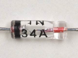
1N34A series
I start off with the realization that when one orders diodes, it is by no means certain what one will get. This seems especially true for the supposedly ubiquitous 1N34A. Unless you see the part number actually on the diode, you probably need to test it to know what it really is. So, lets take a look!
1N34A series
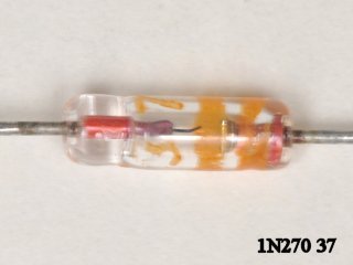
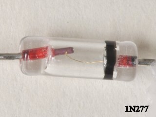
1N270-277 series
ITT Diodes, Something special here.
One oddball Ge diode, not sure what it is for..
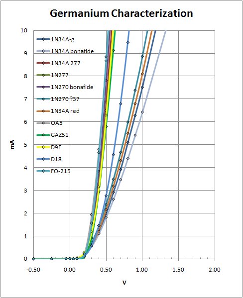
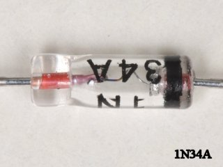
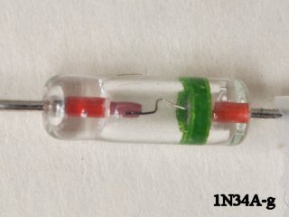
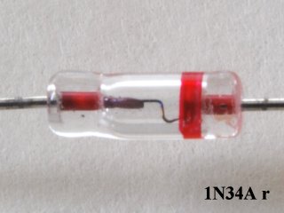
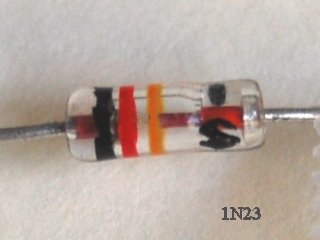
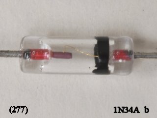
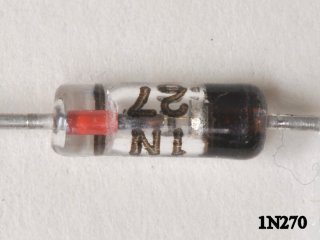
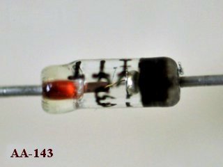
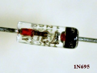
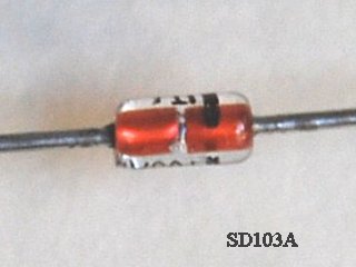
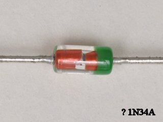
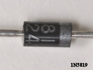
Here we see a set of Germanium diodes and photos of the diodes under test. Immediately you should notice two sets of curves, what I call the "1N34A" set and the "1N270-277" set. In this analysis, the second set appears clearly superior in sensitivity and deservedly so. In the photos it is clear that one bunch of diodes I purchased as 1N34A were in fact better 1N277, the black band and thin gold contact wire as well as common curve unite these. "True" 1N34A's have a more robust contact wire. I also purchased a 1N270 and received pretty orange diodes with the number "37" stamped on it, a fairly robust contact wire and a curve that most closely resembles a 1N34A, go figure. Mercifully, I DID manage to get some bona-fide 1N34A's with the part number on the diode, as well as a single bona-fide ITT 1N270 diode with the part number. These are my base for comparison.
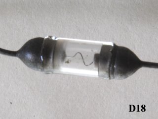
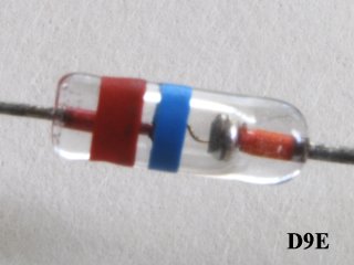
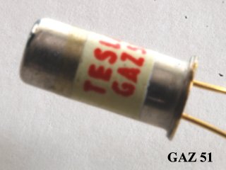
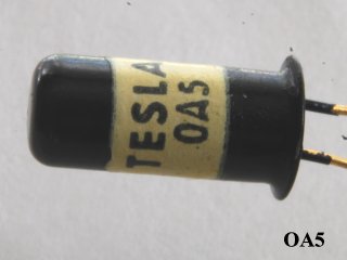
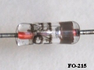
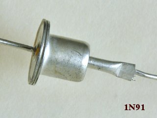
In addition to the standard Germanium Diodes tested above, I also have latched my hands on a few "other" germanium diodes for the fun of testing. These include two vintage Russian types, a D9E (in the 270 class) and a D-18 (transitional between 270 and 1N34A). Additionally, I acquired a few FUZZ diodes popular, I suspect, with the guitar gadget crowd. These are larger packages in metal cases so I cannot see how the internal contact is made other that they are stated to be gold bonded point contact type. Clearly these are highly sensitive diodes in my 270 class, the OA5 looking best of the lot. Interestingly, I recently purchased from good Mr. Peebles a few of his "Holy Grail" ITT FO-215 diodes. My measured characteristic for one of these is a dead lay down on the gold-bonded OA5. From the photos, these are in different packaging with the FO-215 in a traditional glass casing. What makes the FO-215 so great is the fact that its resistance Rd is an interesting 150k ohm or so which matches very well with typical moderate Q tank circuits. Interestingly, I find that an old Russian D18 diode has very similar characteristics to the FO-215 and so must also be placed into the "Holy Grail" class of germanium diode. Take your pick!
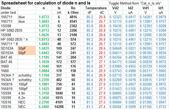
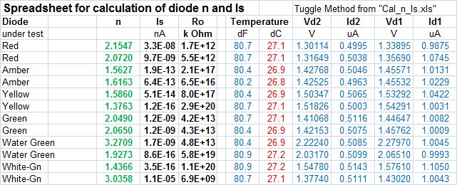
Spreadsheet for calculation of Germanium diode n and Is (modified from Mike Tuggle's spreadsheet)
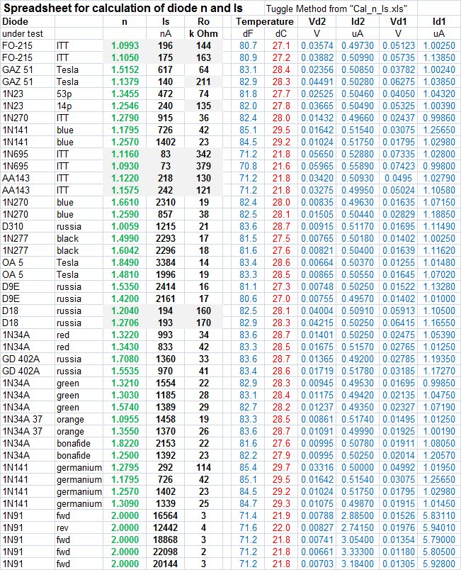
The above spreadsheet is based on measurements of the diodes shown above. For the determination of Is and n, I chose at random two examples from my collection of various diodes, (all germanium in this case) and measured via a modified version of the methodology outlined by Ben Tongue and Mike Tuggle. For this work I have chosen to set Id2 about 0.5uA and Id1 about 1.0uA and then read the needed voltage. This is the inverse of the normal method but the justification is that for any diode regardless of forward voltage drop the measurement is made at the same part of the LOG I vs V characteristic. This allows comparison between all diodes. I have included the actual room temperature in the calculations in order to eliminate this variable as a source of doubt or error. All the measured parameters as well as the determined results are presented in order to facilitate repeatability.
A final note on the plots above. You will have noticed that I sub-divide germanium diodes into a "1N34A" class and a "1N270-277" class. This is a result of looking at their I / V characteristics on a plot of 1 - 2V DC versus 0 - 10mA scale. At such a scale the slope of the characteristic for the 1N270 class remains much steeper than that for 1N34 type diodes. As this is not seen as a distinguishing feature at the small-signal scales looked at here, I judge the chief difference between the two types lies in the diode series resistance Rs. This impacts strong-signals but is of no concern for small-signal DX work. Just so you know.
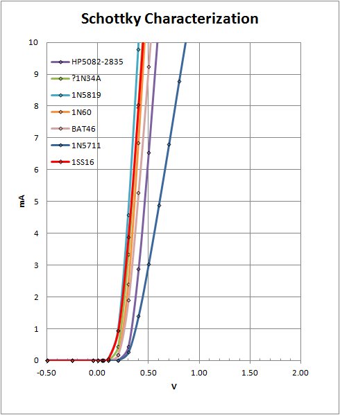
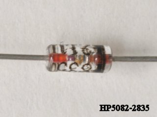
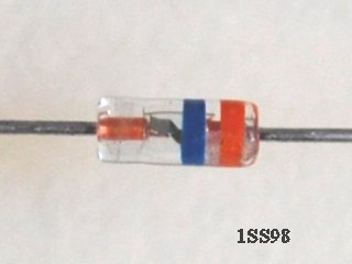
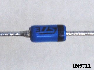
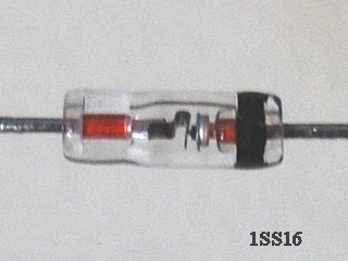
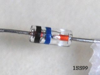
Schottky diodes are very sensitive diodes that work excellently in crystal radios. Their construction and theory are different and I confess to not fully understanding these components. Still, from the characteristic curves, they are excellent! Again, note that you don�t always get what you bargain for. Here I found what was supposed to be 1N34A's to be some sort of Schottky of unknown pedigree. The 1N5819, while having the lowest forward voltage drop, has a rather very high Junction Capacitance and will not perform well. Posts on the RaidoBoard Crystal Radio Forum however highly recommend the 1N5711 for crystal sets although the characteristic curve doesn�t look that fabulous. Many web pages out there on Shottky diodes, I recommend you do your homework. Of all the schottky's, I note that Ben Tongue recommends most highly the HP5083-2835. The high resistance Ro makes them useful for DX sets with very very high Q tanks. Even so the diodes need to be paralleled with up to 4 or 5 diodes to match correctly the Rd with the tank Rp. I have found these somewhat hard to find and expensive, especially when one requires using several in parallel. I recently measured a few 1SS98 diodes and I discover them to have characteristics extremely similar to the HP and I feel they deserve more attention. Sadly, on ebay they seem to be just as difficult to find and expensive. No free ride!
Spreadsheet for calculation of Schottky diode n and Is (modified from Mike Tuggle's spreadsheet)
The above spreadsheet is based on measurements of the diodes shown above. For the determination of Is and n, I chose at random two examples from my collection of various diodes, (all schottky in this case) and measured via a modified version of the methodology outlined by Ben Tongue and Mike Tuggle. For this work I have chosen to set Id2 about 0.5uA and Id1 about 1.0uA and then read the needed voltage. This is the inverse of the normal method but the justification is that for any diode regardless of forward voltage drop the measurement is made at the same part of the LOG I vs V characteristic. This allows comparison between all diodes. I have included the actual room temperature in the calculations in order to eliminate this variable as a source of doubt or error. All the measured parameters as well as the determined results are presented in order to facilitate repeatability.
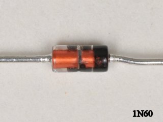
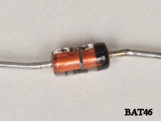
Note in the above data that both the BAT-46 and the 1N60 diodes appear to have excellent properties for crystal radio work. In fact they have very similar parameters overall. Looking at the photos you should also note that the two types of diode look suspiciously exactly alike. The BAT 46 has it correct markings but the 1N60 is unmarked. You never know what you get!
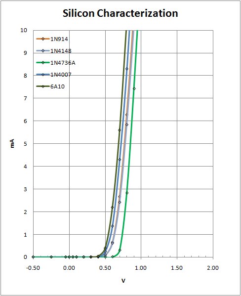
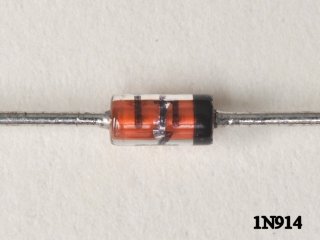
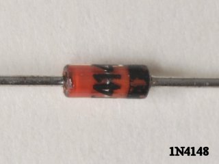
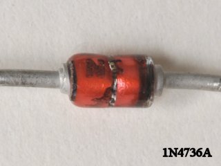
Silicon diodes have good characteristics, but an unacceptably high forward voltage drop making them a very poor choice for crystal radio unless used with bias. The 1N4736A is a Zenner diode.
Spreadsheet for calculation of Silicon diode n and Is (modified from Mike Tuggle's spreadsheet)
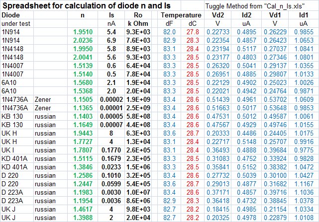
The above spreadsheet is based on measurements of the diodes shown above. For the determination of Is and n, I chose at random two examples from my collection of various diodes, (all silicon in this case) and measured with a modified methodology to that outlined by Ben Tongue and Mike Tuggle. In this case, with the radically different forward voltage drop of these diodes from Germanium or Schottky diodes, I have kept the Id values constant (about Id2=0.5uA and Id1=1.0uA) and varied Vd. I have included the actual room temperature in the calculations in order to eliminate this variable as a source of doubt or error. All the measured parameters as well as the determined results are presented in order to facilate repeatability.
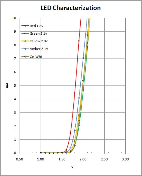
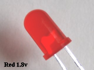
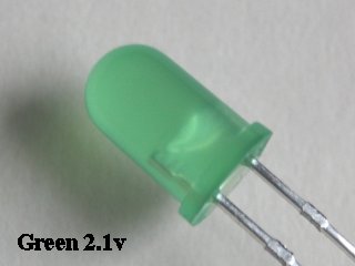
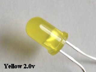
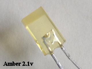
As long as I am measuring various and sundry diodes, I figure I ought to include that most ubiquitous of modern diode, the LED. Found everywhere, these diodes are rapidly becoming the low-energy light source of choice for many lighting applications. I have read occasionally of someone asking whether these ought to be useful for radio applications as well. To this question the answer is generally a resounding "No!". The turn-on voltage is waaay above any reasonable value expected to be delivered by an antenna to a crystal set. Still, this simple answer avoids the actual question, what in fact does the characteristic curve of a LED really look like? Where is the turn-on voltage with respect to the published junction voltage, (assuming you can find that).
To provide just such a look I visited my local electronics store and bought a small handful of LED's, most with the junction voltage listed and took them home to measure. Typical LED junction voltages seem to range from about 1.8v to 2.1v or more. The turn-on voltages look closer to 1.6v-1.7v. Anyone used to working with Carborundum crystals or silicon diodes will be used to biasing their rectifier to get good sensitivity. These LED's once on have a very sharp rise and with a proper bias should work quite well as detector diodes. As a bonus you will get a sweet glow as well. OK, not as cool as the glow of a vacuum diode, but certainly more sensitive!
Spreadsheet for calculation of Light Emitting Diode n and Is (modified from Mike Tuggle's spreadsheet)
The above spreadsheet is based on measurements of the diodes shown above. For the determination of Is and n, I chose at random two examples from my collection of various diodes, (all led's in this case) and measured with a modified methodology to that outlined by Ben Tongue and Mike Tuggle. In this case, with the radically different forward voltage drop of these diodes from Germanium or Schottky diodes, I have kept the Id values constant (about Id2=0.5uA and Id1=1.0uA) and varied Vd. I have included the actual room temperature in the calculations in order to eliminate this variable as a source of doubt or error. All the measured parameters as well as the determined results are presented in order to facilitate repeatability.
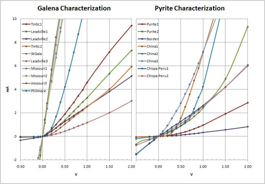
The above curves demonstrate the wide variation in properties and qualities that can be found in natural crystals of galena or pyrite, the two most common and best quality natural stones. In each crystal test I first poked around the crystal for some time to 1) determine a typical sensitivity for the crystal in question and 2) to locate the best hot spot with which to test. This turns out to be a non-trivial exercise on the diode test setup. In a crystal radio one need only listen for the loudest spot. With the test setup one needs test both the forward and reverse current in order to determine if the whisker is on a hot spot or not. Very tedious work! (In retrospect, if I were starting over making a test jig, I would definitely add a DPDT switch to readily change between forward and reverse current measurements. I'd probably toss in a rheostat for fine adjustments as well).
For many crystals there are limited number of possible hot spots, but these may be hot indeed. For most of my "Steel Galena" samples (Tintic Utah, or Leadville Colorado) there are numerous hot spots under virtually every place I touch the probe, but in general the sensitivity is good to so so. These crystals are very kind to work with in terms of finding spots and avoiding frustration. Mirror galena on the other hand may have quality hot spots, but any hot spots at all are rare and frustratingly difficult to locate. Here my Philmore detector crystal shines with an almost ideal "Galena" response. To chase down this rabbit I purchased some lovely mirror galena from Sweetwater Missouri. I broke off a few appropriate-size chunks to pot in woods metal and test. At first I was very excited with the high currents I was seeing at moderate voltages. Figured I had struck gold. When these crystals failed miserably to rectify anything in my radios, I re-measured things in both forward and reverse directions. These crystals obey Ohm's law and act like typical resistors, not suitable for radio work at all.
For my pyrite crystals the work has been especially tedious and frustrating. With one of the crystals one "hot spot" alternated, entirely on its own, between hot and bad while I was making the measurements. I would start over and over, sometimes getting interesting readings then suddenly it would drop to low values and I'd start over, back and forth. I present this data as best as I have measured, and I don't intend to go back! You see at least one of the crystals, my "China 1", (from a lead/silver mine in Hunan) gave a sweet classic-looking curve. More to the point, "ideal" curves for natural minerals are difficult to come by. Most crystals you use will be less than ideal. The good news is that, while listening to your set, poking about for a good spot is far easier than what I have gone through to produce these curves. Your ear will take care of you!
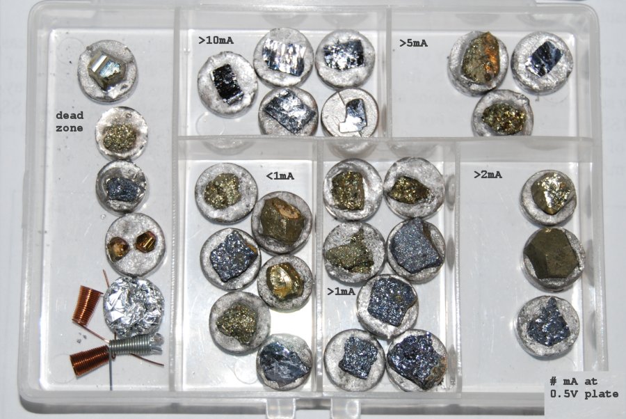
In the photo I indicate groupings based on an easy measure of performance. I note the current in milliamps for each set where the plate voltage is set at 0.5V. The greater the current the better are your chances to get a sensitive crystal, assuming Ohm's Law is not followed! Crystals in the "dead zone" on the left will have their woods metal re-melted for new detector crystals and the bad ones tossed, its tough love for crystals. I find that easily half the potted crystals I make are tossed this way, and only a few can be considered superlative.