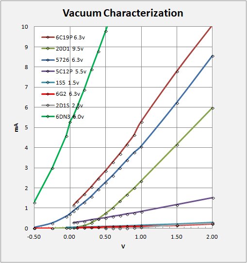
When I decided early on to construct a radio based on the vacuum diode (see my Fleming Radio section), I had to find a suitable tube for the project. That began with an extensive search through the datasheets checking vacuum diode properties and reviewing the characteristic curves for a large number of diode tubes. In the above figure I plot the characteristics as best I can on a common plot for comparison. I was hoping to find a good candidate with sensitive characteristics and low energy consumption. As you will find, such a beast did not exist. Following this research began a period ot purchase and testing.
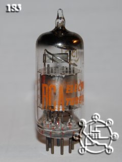
I have tested seven different tube types including 6.3V rectifier diodes that take a lot of power to run and are not really suitable for battery use, a 9v dual diode tube (20D1), a pentode/diode tube (1S5) that is designed to run on a battery at 1.5V and 50mA, and a couple miscellaneous but cute tubes. In testing the 1S5, I found the filament never glowed incandescent at 1.5V and, on measuring, was barely sensitive to anything. I cannot imagine this tube would make much of a diode for crystal radio use. I tested different manufacture 1S5 tubes from two different suppliers. No dice. Finally, I tried to push the tube to operate at higher-than-specified voltages. At 4.3V the I-V curve was still very flat, but shifted slightly higher, crossing the Amp axis at about 0.4 mA, (see graph). At 5.5V one of my tubes gave up the ghost and I didnt do more. I pretty much rule the 1S5 out for my crystal radio work. Looks like i'll be needing the power supply when I get around to building/operating that Fleming Radio.
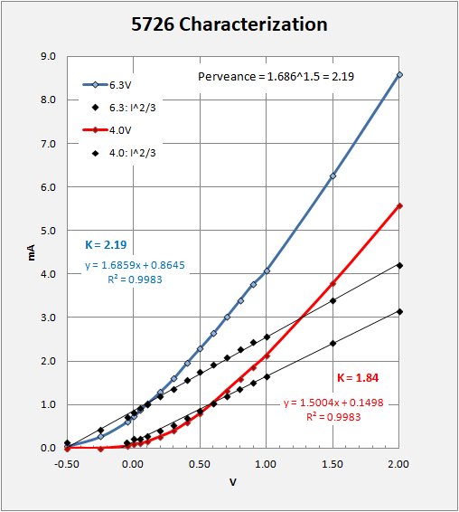
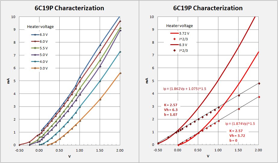
A question remains as to what in fact is different about these tubes to give such different characteristics. While the I/V characteristic of most vacuum diodes pretty much follow the Langmuir-Child Law, the steepness of the I/V characteristic is largely due to the geometry of the tube elements and the volume of electron space-charge between them. JB Calvert's Theory of Vacuum Tubes informs one that this is the property called Purveance in a vacuum diode. Measuring this requires plotting I raised to the 2/3 power against V and taking the slope of the best-fit line through the data. This slope raised to the 3/2 power is the perveance. The following chart illustrates graphically the relation between the tube characteristic and perveance. For the 5726 tube I plot the characteristic in dark blue for the tube heated with the design 6.3 volts. In light blue I have plotted the measurements and raised them to the 2/3 power. One sees immediately that the new curve is linear. The slope of the curve raised to the 3/2 power yields the perveance factor for the tube.
(Note in addition that when running the tube at a more sensitive point with 4 volts only on the heater the perveance is slightly less than spec.).
In addition to the above definition for Perveance there are two other aspects of vacuum diodes that need to be defined. These are 1) The Splash current and 2) the Contact potential.
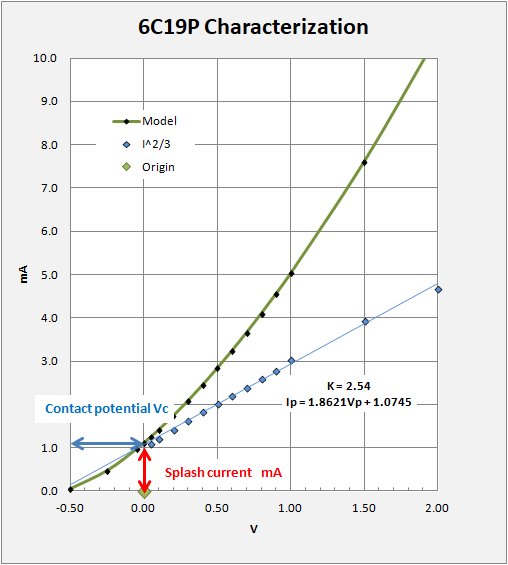
Splash current is the current across the diode with Zero voltage applied to the plate. Normally one thinks of a diode where the characteristic curve passes through the origin (0,0) of the I/V chart. This is true for solid state diodes. With vacuum tubes there is an electron space charge in the region between the Cathode and Plate (Anode). A certain number of electrons leave the heated cathode with sufficient velocity to carry to the plate and cause a measurable current. With higher perveance tubes the plate area is large and the spacing is small, therefore a fairly large current may develop at Zero applied voltage. In the case of the 6C19P operating at its spec 6.3V on the heater, the splash current is quite high at just over 1 mA. This is death to small signal rectification.
Contact potential represents how negative the voltage must be before the current becomes zero. That is, the amount of negative voltage needed in order to reduce the splash current to zero. The 6C19P has a large contact potential of just over 0.5V negative. Not even strong local signals can overcome this!
For efficient small-signal rectification, one seeks high perveance with both splash current and contact potential at zero, and a steep characteristic passing through the origin.
With my measurements calculating the perveance is practical and quickly done, results as follows:
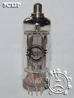
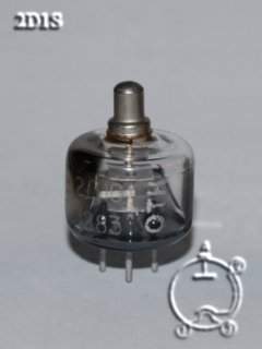
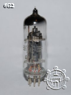
Tube	Perveance	R2
6C19P	2.54		0.997
5726	2.19		0.998
6DN3	5.40		0.997
20D1	2.02	LC?	0.985	(may not follow Langmuir-Child)
5C12P	0.32		0.999
1S5	0.063		0.999
2D1S	0.155	LC?	0.975	(may not follow Langmuir-Child)
6G2	0.050		0.999
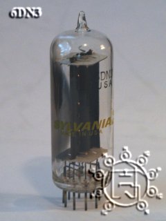
The perveance numbers above range from 0.02 to over 2 mA/V^3/2 (with >2 being good for small-signal detection) and clearly shows my choice of the 6C19P to be an excellent one. I am surprised to see a huge 5.4 for the 6DN3 diode, a color television damping diode. It takes a Novar 9-pin socket and is a large tube so doing more with this tube may have to wait a bit.
Calvert's 2001 published data
Tube	Perveance
6AL5	2.42
6H6	0.50
7Y4	0.58
2X2A	0.017
6V3-A	2.3
6AX4GT	1.42
6AV6	0.085
1A3	0.075
The high-perveance diode tube types I tested show an interesting property in that their characteristic curves do not pass through the origin of the graph. These curves are wholly acceptable as crystal radio detectors although they will require power to operate. What I have noticed with such tubes is that when I turn them off after using them with a radio, on cooling they go through a period of much increased sensitivity (very loud) before fading to nothing. It is as though running them at the full 6.3V lowers their full potential as crystal radio rectifiers. The reason is in the high perveance of the tubes, the anode is already proximate to the space charge before any plate voltage is applied. Effectively, while the plate (anode) "Zero" voltage is measured with respect to ground, the plate itself is still positive with respect to the cathodic space charge. Small currents will continue to flow even with a negative bias to the plate, (Contact potential).
In order to explore this idea, I ran a series of tests with the tubes running at lower operating voltages (effectively diminishing the space charge thus lowering the splash current) as shown:
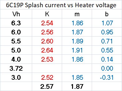
Here you see the impact of lower operating voltages. With the tube operating between 3 and 4 volts the characteristic curves begin to pass through the origin as in regular solid-state diodes and crystals. It is precisely in this voltage range that I found the radio sensitivity, as measured by loudness to my ear, to be most pronounced. The diode characteristic needs to pass through the origin of the I-V chart for rectification at highest sensitivity. Having ran characteristics on the 6C19P at various heater voltages (Vh) I am able to calculate the Perveance (K) and the Splash current (b) for each curve, summarized in the table above. In the table: K = perveance, m = slope (raised to the 3/2 power = perveance), and b the splash current. You should note immediately that the perveance of the tube (K) DOES NOT CHANGE with differing temperature. This is because the geometry of the tube does not change. What does change is the position of the curve on the chart such that with lower temperatures the curve have a lower Y intercept. I plot the splash current heater voltage to demonstrate a linear relationship. With this I can readily calculate the heater voltage that provides a Zero intercept. Thus 3.72 V is the ideal operating voltage for efficient rectification using a 6C19P vacuum diode.
If you have tried a vacuum diode on your crystal receiver and run it at its spec temp (6.3V for many such as the 6C19P), you have more than likely been disappointed with the results. Pull that old set off the shelf and try again while adjusting the heater temperature to a lower level. You may be surprised by what you hear.
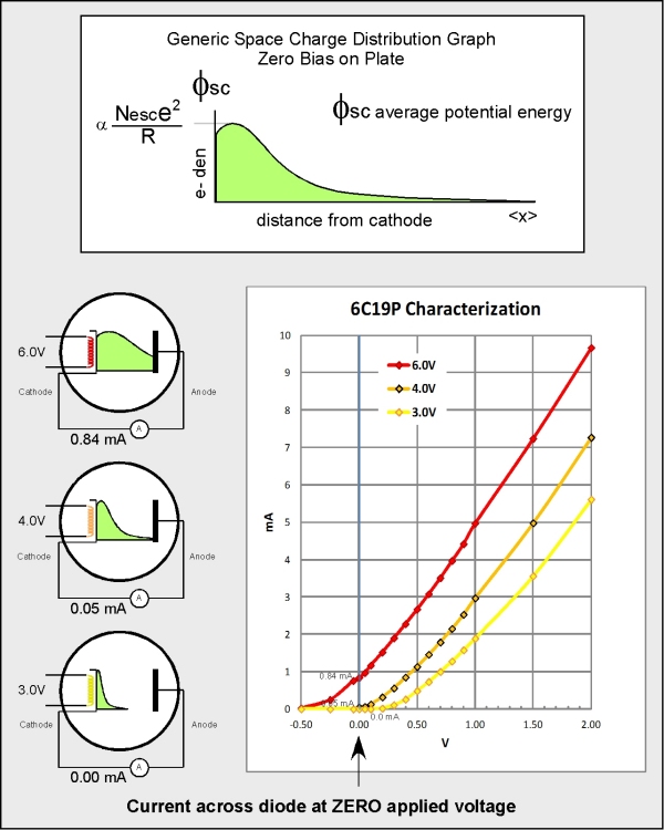
A conceptual look at the impact of heater temperature on the space charge distribution in the annulus between cathode and anode. I start by drawing a qualitative plot of charge density versus distance from the cathode. This is not how such plots are done in the literature but it is a nice visualization. The distribution of charge is a statistical function of heater temperature and plate bias. For the zero-bias case I show qualitative distributions for three heater voltages, 3.0, 4.0, and 6.0 volts. On my chart of current/voltage I find no current flows with 3.0 volts on the heater. Current just begins to be measurable at 4.0V and at 6.0V I found a significant 0.83mA of current indicating that a good portion of the space charge is not impinging on the plate even with zero bias.
Biasing the plate positive will have the effect of "pulling" the space charge towards the plate increasing the current while a negative plate bias will have the opposite effect. With 6.0V heater it will take nearly a negative half volt before the current stops. This is death to sensitivity in a crystal set. Operating the heater at 4.0V provides the most efficient rectification.
Note also that high perveance is not merely a matter of placing the plate as close as possible to the cathode. This may cause an excessive zero-bias current to overcome. The surface-area of both cathode and plate are also critical with large areas providing high current transfer. Vacuum tubes such as pentodes with an included diode plate are poor rectifiers having very low perveance. This is due to the small plate stuck in with all the other hardware in the tube. Get a "fit for purpose" diode for best results.
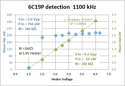 Note that while the above model as well as hearing (a kind of "hearing is beleiving" thing) supports the 4.0V heater voltage as a sweet spot for highest rectification efficiency, I have yet to be able to measure this. Using my tube-driven Telefunken set (see description on my main radio page) I made a series of output signal power measurements at various tube heater voltages. In this I found no relation between matched output power and the tube heater voltage at 20mV input (2.0Vpp on signal generator), and a monotonic increase in output power at 6mV input (0.2Vpp on the generator). I was seeking a peak output power at around 4.0V on the heater so this result is disturbing. I can hear it, but cannot measure it.

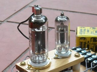
Portraits:
The following spreadsheet provides my entire 6C19P observations and evaluation. Plate voltage (Vp) is on the lefthand column, observations, models and calulations after that by heater voltage (Vh). The first spreadsheet gives the observations and their models. In the second spreadsheet I model and compare the 6C19P run at operating spec 6.3Vh, and at the "ideal" operating Vh = 3.72V. These are the data behind the 6C19P Characterization charts presented above.
6C19P Observations and Models
	6.3 V			6.0 V			5.5 V			5.0 V			4.0 V			3.0 V			= Vh
Vp	Obs	Model	I^2/3	Obs	Model	I^2/3	Obs	Model	I^2/3	Obs	Model	I^2/3	Obs	Model	I^2/3	Obs	Model	I^2/3
		2.541			2.559			2.604			2.636			2.531			2.524		= K
		1.862			1.871			1.893			1.908			1.857			1.854		= m
		1.075			0.948			0.713			0.547			0.135			-0.312		= b
		-0.577			-0.507			-0.377			-0.287			-0.073			0.168		= Vc
-0.50		0.05	0.14	0.02	0.00	0.01
-0.25		0.48	0.61	0.25	0.33	0.48	0.05	0.12	0.24	0.03	0.02	0.07
-0.05		0.97	0.98	0.76	0.79	0.85	0.40	0.49	0.62	0.25	0.30	0.45		0.01	0.04
0.00		1.11	1.07	0.84	0.92	0.95	0.63	0.60	0.71	0.31	0.41	0.55	0.05	0.05	0.14
0.05	1.15	1.26	1.17	0.97	1.06	1.04	0.65	0.73	0.81	0.46	0.52	0.64	0.06	0.11	0.23
0.10	1.34	1.42	1.26	1.17	1.21	1.14	0.82	0.86	0.90	0.61	0.63	0.74	0.13	0.18	0.32
0.20	1.69	1.74	1.45	1.52	1.52	1.32	1.15	1.14	1.09	0.90	0.90	0.93	0.32	0.36	0.51	0.02	0.014	0.06
0.30	2.07	2.09	1.63	1.90	1.85	1.51	1.50	1.45	1.28	1.21	1.19	1.12	0.56	0.58	0.69	0.11	0.121	0.24
0.40	2.48	2.45	1.82	2.28	2.21	1.70	1.84	1.78	1.47	1.55	1.50	1.31	0.85	0.82	0.88	0.26	0.282	0.43
0.50	2.86	2.84	2.01	2.67	2.59	1.88	2.22	2.14	1.66	1.91	1.84	1.50	1.13	1.10	1.06	0.49	0.483	0.62
0.60	3.29	3.24	2.19	3.08	2.98	2.07	2.61	2.51	1.85	2.30	2.20	1.69	1.46	1.40	1.25	0.73	0.717	0.80
0.70	3.71	3.67	2.38	3.51	3.39	2.26	3.02	2.91	2.04	2.66	2.58	1.88	1.79	1.72	1.44	1.00	0.979	0.99
0.80	4.17	4.11	2.56	3.97	3.82	2.44	3.46	3.32	2.23	3.08	2.99	2.07	2.15	2.06	1.62	1.28	1.268	1.17
0.90	4.64	4.56	2.75	4.42	4.27	2.63	3.90	3.76	2.42	3.49	3.41	2.26	2.53	2.43	1.81	1.58	1.580	1.36
1.00	5.30	5.03	2.94	4.97	4.73	2.82	4.41	4.21	2.61	3.95	3.85	2.46	2.97	2.81	1.99	1.89	1.915	1.54
1.50	7.79	7.61	3.87	7.24	7.27	3.75	6.60	6.70	3.55	6.15	6.30	3.41	4.98	4.99	2.92	3.56	3.880	2.47
2.00	10.08	10.51	4.80	9.67	10.16	4.69	9.12	9.54	4.50	8.94	9.12	4.36	7.27	7.55	3.85	5.61	6.258	3.40
6C19P analysis
	6.3 V		3.72 V		= Vh
Vp	Model	I^2/3	Model	I^2/3
	2.541		2.566		= K
	1.862		1.874		= m
	1.075		0.000		= b
	-0.577				= Vc
-0.50	0.05	0.14
-0.25	0.48	0.61
-0.05	0.97	0.98
0.00	1.11	1.07	0.00	0.00
0.05	1.26	1.17	0.03	0.09
0.10	1.42	1.26	0.08	0.19
0.20	1.74	1.45	0.23	0.37
0.30	2.09	1.63	0.42	0.56
0.40	2.45	1.82	0.65	0.75
0.50	2.84	2.01	0.91	0.94
0.60	3.24	2.19	1.19	1.12
0.70	3.67	2.38	1.50	1.31
0.80	4.11	2.56	1.84	1.50
0.90	4.56	2.75	2.19	1.69
1.00	5.03	2.94	2.57	1.87
1.50	7.61	3.87	4.71	2.81
2.00	10.51	4.80	7.26	3.75