Hammarlund, Double-Tuned
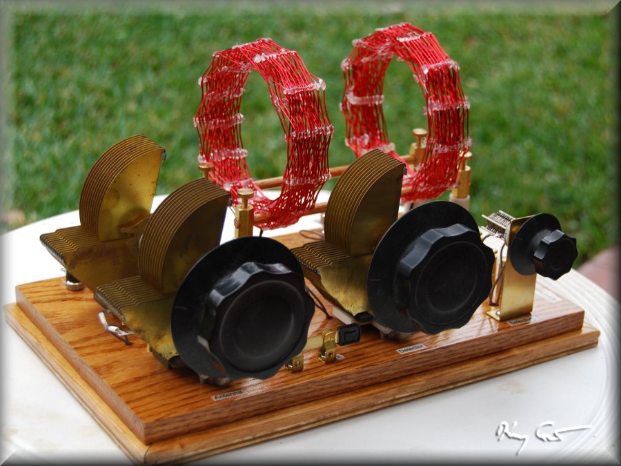
This fine radio features three beautiful and high-quality Hammarlund square-law 510pF variable capacitors. I have been hankering for some time to build a radio with more than just OK to mediocre performance, which translates to a double-tuned set with a properly tuned front end. The capacitors mentioned before were, at first, a poor choice for this project as I needed for the antenna tuner a two-ganged variable cap and the Hammarlund units were only single. Additionally, I only had one! With what I can only call considerable luck, two additional identical capacitors were listed over the last several months on ebay giving me three total. The caps are high quality and very heavy construction and I figured I ought to be able to dismantle them enough to give a common shaft to two thus ganging them as needed. This turned out to be the case and the project was a go.
 Additionally, with each radio I build, I like to test and learn new circuit concepts and ideas. This radio was to be made with a farily simple double-tuned circuit, a tuggle-tuned front end and variable coupling. I also wished to test and play with the "Hobbydyne" or selectivity enhancement ideas presented by Dave Schmarder on his excellent site. I had tried this before on a version of an MRL-2 but it was a disappointment, not the right set for the test. As this set was to employ a high-performance circuit, an SEC would be appropriate. The set itself is only moderate performance though, the caps having fairly high-loss brass plates and my coils wound with solid wire. This set also ploughs new ground for me in my first basketweave coils. Basketweave coils recuce stray capacitance and increase coil Q by eliminating the need for lossy coil formers. As these were my first, I merely used solid wire I had in the house. As they are wound of 20awg solid wire, they are quite springy and I had to hot-glue the bejeezes out of them to get them to stay put. I do one day expect to build a truly hi-performance set, but this is just a stepping stone to test components and design. As such, I tossed a benny into the circuit for good measure.
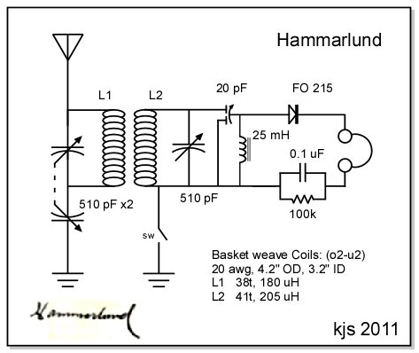
The design calls for non-tapped coils to increase coil Q. While the coil Q is not great, it is certainly considerably better than any of my earlier cardboard tube or even PVC selonoids and it ought to have a decent tank parallel resistance. Matching (hopefully) to this I used a germanium FO-215 diode from Mike Peebles. The combination in these diodes of low n (~1.1) and Is (190) gives a diode with moderately high junction resistance on the order of 150+ kOhm which should work well with the solid-wire coils in the tank.
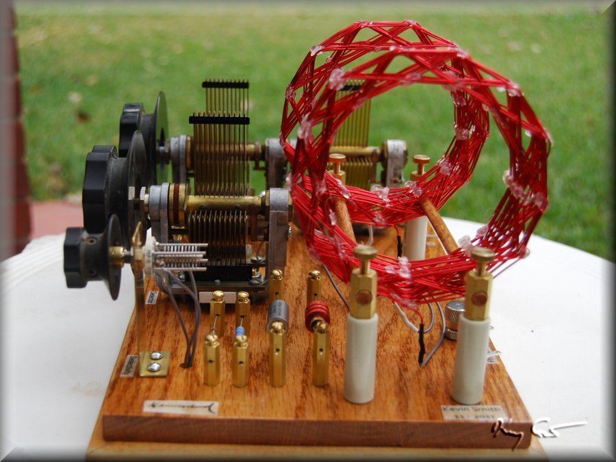
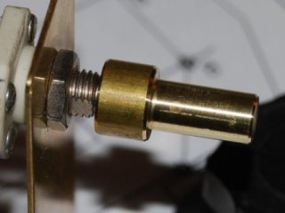 The selectivity enhancement circuit called for a cool 20pF differential cap which I found at Surplus Sales of Nebraska. The cap itself is a cute little item but the shaft was a short 1/4in long and only 0.19in in diameter. Something was needed here! At left is a photo of a very sweet brass shaft converter machined by my clever and capable EE elder brother, many beaucoup thanks for your addition to the project! Not being an engineer myself I was able to follow very poor practice and just wired the whole lot together, crossed my fingers and hooked the sucker up.. Ya Hey! There be sounds here!
The set is playing as I type these words and I am most hopeful for a successful performance goal. Although much testing and measuring yet remains to be done, the set by ear calibration tunes quite sharply. The coils have 4.2 inch OD and 3.2 inch ID and can slide upwards of 4-5 inches separation for looser coupling.
The selectivity control has a dramatic effect on sensitivity and, I am sure, on selectivity as well.. to be measured soon so stay tuned.
The photos below present the set in its final functionning form.
A few words of the performance of my Hammerlund set are in order. When I first started using the set I noted with satisfaction that, by my eardrum meter, the set seemed to indeed tune quite sharply. This is certainly my principal goal in making this double-tuned set. The only fly in the ointment was that the radio seemed quite insensitive, the stations coming in very weakly and needing amplification. The SEC control did have an interesting and dramatic effect when used, but it also hugely lowered an overall low sensitive set. With these thoughts in mind, I have spent some time making some preliminary measurements on the sets' resonance, sensitivity and selectivity.
To characterize the set completely, I measure under a number of different cases. I wish to test the effect of the selectivity enhancement circuit (SEC). The SEC uses a 20pF differential capacitor which places the capacitance either 1) in series with the top of the tank and detector, or 2) shunted parallel across the tank. I make a full set of measurements with the SEC cap set fully to each the series and shunt positions. The above paired measurements are made for each of three coil coupling positions. The two coils can be shifted along two rails to bring them from essentially touching to a maximum separation of about 10 cm, or about one coil diameter. This is the max separation obtainable on my breadboard as the Hammarlund caps are quite large and take up much space. To evaluate the impact of coupling, I measured with the coils separated 1cm, 5cm and the max 10cm.
OK, enough with the preliminaries let’s look at the data!
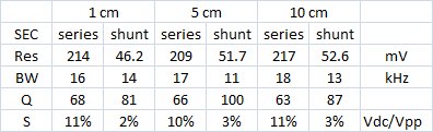 The table at left presents the measurements (Res = resonant peak Vout mV : BW = bandwidth and -3dB : Q = under load : S = sensitivity = Vdc/Vpp) vertically and the different cases horizontally. Bandwidths for the cases all range between 16 - 18 kHz for SEC in series and 11 - 14 kHz for SEC in shunt. These are pretty good numbers for a standard (non-DX Contest) rig and correspond to Ql in the 65 - 85 range. Context for this comes from Ken Khun's excellent engineering pages where he notes for crystal sets that loaded Q normally ranges between 10 (poor) to 50 (typical) to 100 (very good). My set here then is pretty good in this respect and confirms my eardrum assessment above.
Sensitivity on the other hand, well, it sucks. 2 to 11 percent Vdc/Vpp are very low numbers, many of my single tuned sets range from S = 10 to 50 and my Minstrel Boy getting over 60 percent. What happened? The data show the SEC to be involved here. Note that with capacitance in series the sensitivity is about 10% but when
shunted across the tank the selectivity improves, but the sensitivity crashes down to 2-3%. I really expected better for this set. This is my second double-tuned rig, my first was a simple set using solid magnet wire close-wound on 3" cardboard cores and having 6 twisted taps, all Q lowering. This sets' coils have no taps and no
cores and ought to have significantly better Q. The primary difference between the two sets is the presence of the benny and SEC on my new set. I am worrying about insertion losses more than offsetting the improvements in the coils.
The severe loss of sensitivity when using the SEC on this set also reminds me of my experience with my Fleming set, a modified MRL#2 using SEC. There I also found loss of sensitivity when the SEC was in the circuit. At the time I concluded that the circuit was inappropriate for testing the SEC concept, now I am not so sure. This set
employs a high-performance circuit (if not high-performance parts) and is fully correct for the SEC inclusion. One additional test I intend to make when time allows is to completely remove the SEC and Benny ornamentation from the set and re-test the sensitivity. I suspect that insertion losses are killing me. Dave Schmarder has the
most experience with this design feature, I wonder what his thoughts are? Have you tested a set with and without the SEC? What have you found? I am suspicious of this feature now.
A few words on resonance: When making my measurements I noted a curious effect in the resonance curves. They became increasingly asymmetrical with wider spacing of the coils and actually had a double hump at the maximum spacing of 10 cm. This is the exact opposite of how I expect resonance to work. I set to measuring the Vout across a significant portion of the MW band for each of the coil separations and present a graph below:
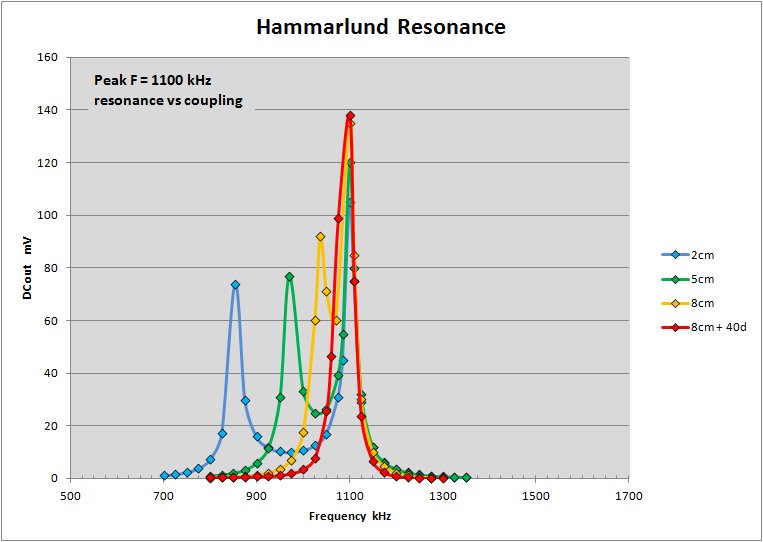
It should be readily apparent from the above graph that my set is badly over-coupled even at its widest separation of 10cm. I suspect critical coupling for the set is with a coil separation in the 15 - 20 cm range. Yet one more design consideration to keep in mind when making a new set! The double hump causes two problems for the set, one: it tunes each station twice and two: has the possibility to bring in two stations at the same time if they have the right separation on the band. Both these effects I can easily hear when tuning the set. Oh well.. Better be forewarned next time! This does not necessarily mean that double-tuned rigs MUST be built in modular fashion with separate tuning and detection units, but it certainly suggests it.
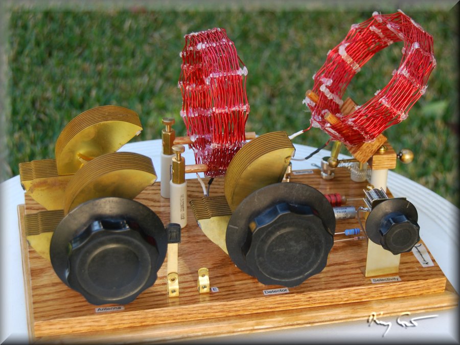
With the lack of surface real-estate to lengthen the coil separation, I made a small modification on the set as seen in the third photo above. There you see the possibility to rotate the outer coil away from vertical thus further lowering the coupling. I can get a max 40 degree rotation which just gets the coils to critical coupling. No more ghosts on the band! Still, I think my next double-tuned rig will indeed be modular. Experience is such a good teacher!