data and information on the set is not small, but not enough:
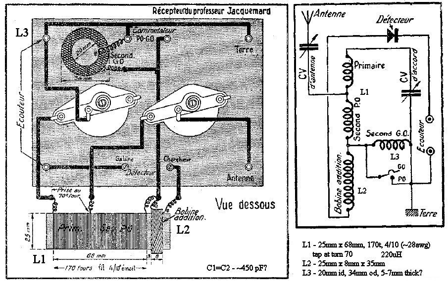
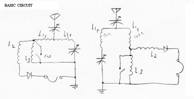
from the schematic:
L1: form 25mm dia, 68mm long selenoid, 170 turns 4/10 wire
calculation- 0.4mm-26awg wire, 220uH coil
L2: ID 25mm, W 8mm. OD, #turns, guage not given
L3: ID 20mm, OD 34mm. W, #turns, guage not given
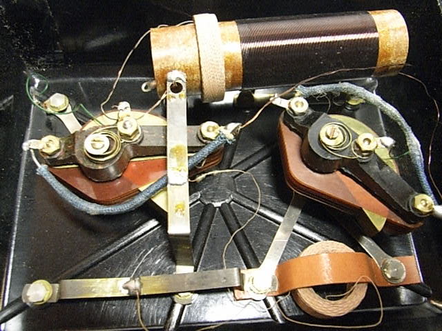
estimation from photo:
L2: OD about 32-35mm, wire guage is small in the 32+ range
L3: W maybe 6-8mm, wire guage is small in the 32+ range
from book:
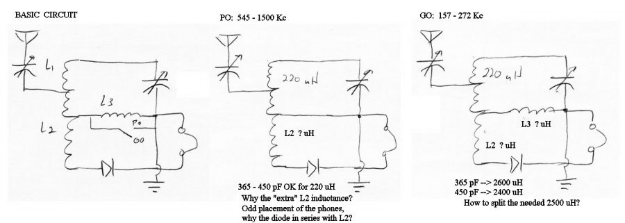
MW = 545 - 1500 Kc
LW = 157 - 272 Kc
from calculations:
MW tuning with 220uH typically 365 - 450 pF
from clues in the two publications
1. most Vcaps are 450pF
2. most GO coils 120turns x two coils
calculations from above:
LW tuning with assumed 450pF cap is 2300 - 2400 uH
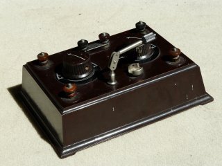
The following photos show the set and the references mentionned above.
(some useful translations for my anglophone friends:
PO = Petits Ondes = Short waves [so named prior to the utility of the HF bands was known]
GO = Grandes Ondes = Long Waves
Bobine Addition = Additional Coil)