Impedance Matching Transformers.
This page presents my notes, calculations, and web research concerning audio impedance and matching transformers. As I am in the process of building one of these big boys, I thought it time to set some expectations, to convince myself that this is an important addition to my crystal radio toolkit. My purpose here is to look closely at radio tank impedance / load resistance (what I have actually measured), and also to compare this with web research on headphone impedance (which I have certainly not measured). All data being presented on "Tank impedance" is based on measurements I have made on my own radios, this therefore may not be completely representative of what is possible, but ought to give a good range. I will present calculations and summary statistics that I feel describe the situation for the radio tank and, separately, also for headphones. This should go far to set expectations.
Tank-Diode Impedance:
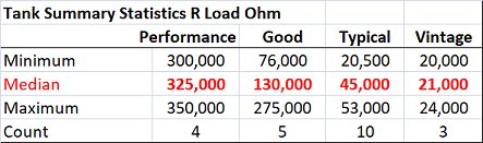 The chart at left gives summary statistics for a number of tank load resistance for maximum power transfer to the audio circuit. The full database can be found near the bottom of this page for some 22 measurements on various crystal sets I have built and tested. I have, somewhat arbitrarily divided the data into four categories "Performance sets", sets made with "good practice", Typical hobby sets, and Vintage sets / sets made with vintage components. Performance sets are expensive, made with the best available components and techniques including 660/46 Litz wire, basketweave coils, ceramic-insulated air-variable capacitors, silver plated if possible, and schottky diodes. Good practice sets include sets with large-gauge magnet wire, minimal taps, "square" coils preferably basket-weave or with low-dielectric forms, "good" germanium diodes such as FO-215 or D-18. Typical hobby sets consist of sets with close-wound and tapped solenoids, often on cardboard forms, small gauge magnet wire, 1N34A / 1N277 or equivalent germanium diodes. Finally, vintage sets are similar to hobby sets but with older vintage components, actual galena crystals. Sets in all these categories are interesting and deserve a place in your consideration.
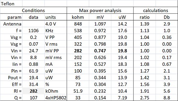
In order to generate the Tank data, I have made extensive measurements on all the radios I have built in different configurations. Please see my section on "Radio Test" for a full description of my protocols and techniques. One aspect that is important for the subject of audio impedance matching concerns how I measured the optimum load resistance so I will give some context here. Most/All measurement protocols I have reviewed online have the output voltage measured across a single resistor in order to peak the voltage and insure the radio is tuned to resonance. This is as far as they go. With the resistance and voltage it is possible to calculate the power output, but this is not necessarily the optimum load resistance for maximum power transfer. In my own protocol, I first peak the output voltage, then I measure the resonant voltage across 10-12 resistors from a few kOhm to a few 100k ohms. Entering the voltages into a spreadsheet allows me to easily assess the resistance for maximum power transfer. Here I make the assumption that the resistance found is equal to the impedance of the take under load.
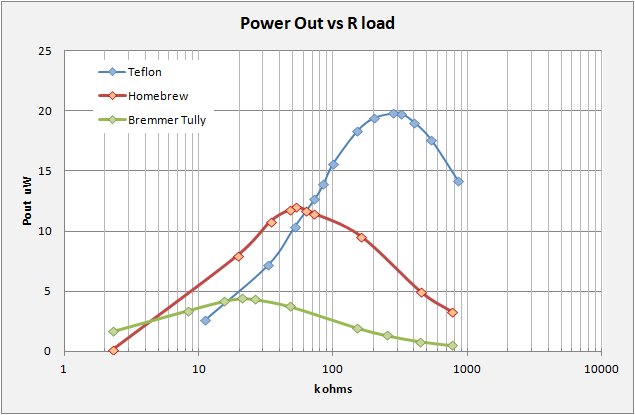
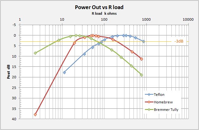
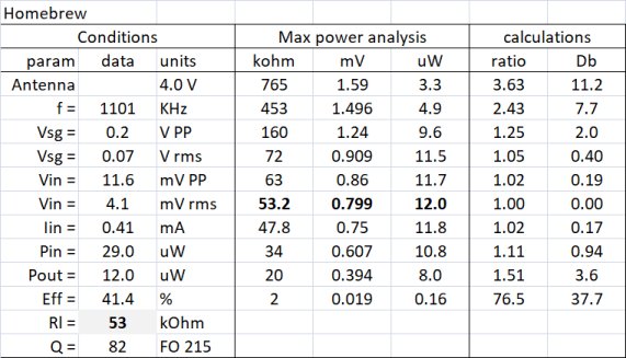
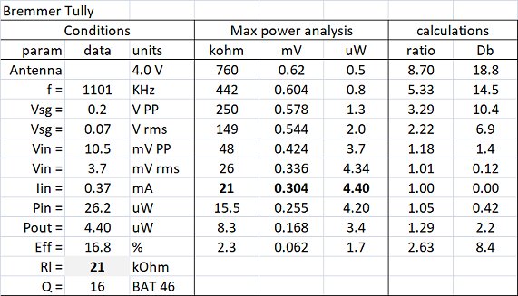
The following two charts show the relation of power output (in uWatts and Decibels) to the load resistance for three different sets, one vintage Bremer-Tully, a Typical hobby set, and a modest performance set made with teflon-coated silver plated coil wire. The variations in optimum load resistance between the three sets are striking. Optimum load varies from 290 kOhms for the Teflon set, 50 kOhms for the Hobby set, and 20 kOhms for the vintage set. For a given set of phones, impedance matching will be required!
It should be pointed out that for most listeners, a drop of 3dB or more is needed in order to hear a difference in sound. This is why I include the dB chart. You should note that the curves are rather flat near the optimal crest and you can tolerate quite a LOT of mismatch between your set and phones before you will hear the difference. The range of phone impedances tolerated assuming the -3dB limits coveres a full magnitude as follows:
		min - med - max
Bremmer Tully 	 7  -  20 -  70 kOhm
Homebrew 	20  -  50 - 200 kOhm
Teflon 		90  - 300 - 900 kOhm
Typical crystal set phones have impedances in the 10-20 kOhm range (more on that below) and will match well to low-end and hobby sets. For performance sets matching will nearly always be needed/desired.
Headphone Impedance:
I have no measurements on headphones, it is not an area I have pursued and I do not have many phones to measure in any case. All the following will depend on what I have scooped up off the net, especially I give thanks to : Darryl Boyd (Stay Tuned site), The Radio Board, and general web searches, especially for data on modern low-impedance phones.
One note and reminder, I present all impedance measurements as Z AC. At least I try to and assume this is correct. Published data on headphone impedance is notorious for giving DC resistance only and not stating that fact. I have tried to "get it right" but can offer no guarentee. Modern Magnetic phones in partictular I have accepted the data as AC. Hope so!
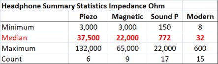 As with the data on Radio tanks, here I have again divided the data into four categories: Piezo element phones, Magnetic phones, Sound Powered phones, and Modern Magnetic phones. The summary table at left shows the large range in phone impedance one encounters. Piazo and Magnetic phones generally are "high-impedance" at several 10's of kOhms. Sound powered phones are in 100's of Ohms and Modern magnetic phones are low-impedance at a few 10's of Ohms. Recall that even the lowest tank impedance has a few 10's of kOhms so all Sound Powered and Modern phones will require matching to just about any crystal radio you are likely to encounter. Piezo elements generally are somewhat higher impedance than Magnetic phones, but I was surprised to discover that these can still be surprisingly low. I have included the main source of information for each entry in the main data table below.
Modern magnetic phones are generally shunned in the crystal radio hobby given their very low impedance. Cheaper phones can indeed have impedances as low as 8 Ohms. Most have impedances around 30 Ohms and can range up to 600 Ohms, in the realm of Sound powered phones. Additionally, as most modern electronics are battery-powered, they are generally designed to be as efficient as possible. For phones this translates to high-sensitivity. With proper matching they should be worth a try. Really..
Note for both summary tables, I include the range and median value, all values in Ohms. I do not consider my data sufficiently complete to give a representation of an "average" value.
I hope this page has given an interesting first look at tank and phone impedance data and helped set your expectations. If you have invested much time and treasure in crystal radio, you will probably be using matching eventually. This information may get you started!
Discussion:
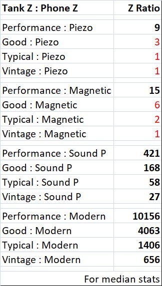 From the above discussion and data below for variations in both tank and headphone types some broad conclusions may be drawn. I have taken the ratio of Tank Z to Phone Z for the median values in each category. A perfectly impedance-matched setup should have a ratio of 1 (or 1:1). On the ratio table at left it is apparent that we may be trying to connect tanks with phones that are badly mis-matched to each other. Sound Powered and Modern phones with a typical impedance of around 800 and 32 ohms just cannot be connected without matching to any crystal radio.. period! On the chart I have highlighted in red those cases where a small ratio may allow a direct connection. Here I am pretty much allowing a mis-match of up to 6:1 or so, this is because I believe the power loss in dB may not be noticable, (see my charts above). Perhaps I should stop at 3 or 4:1 or elsewhere, so shoot me. High-impedance Piezo and many/most Magnetic phones will connect to most crystal sets with little mis-match problem. For Performance sets you will require transformation. The same is true if you wish to use Sound Powered or Modern phones with ANY crystal set.
All these numbers are based on my own crystal tank measurements and my web researches on headphone impedance. They may not be statistically complete, but I feel there is enough data with which to draw the above broad conclusions. This should provide some good expectations when used for your own set design needs. I hope it helps.
R DC versus Z AC:
DC resistance to AC impedance, some forumlae and rules of thumb. These may not be exact but hopefully will get one into the "ballpark", good enough for government work, and more to the point, will allow some expectation setting. That finally is what this section is all about.
* Ceramic / Piezo:
Rochelle salt and Ceramic elements both utilize the piezo effect and so work basically the same way. Ceramic elements are presumably more stable, especially in higher-humidity environments.
These elements are high impedance for DC and that is oftten the published value. AC impedance is less than DC and may be calculated/approximated if you are able to measure the phone capacitance. The formula goes thus:
Z AC (kohm) = 1/(x.xx uF x 2 x 3.14)
A possible rule of thumb, my 20Meg DC phones are reported to have 10kohm AC impedance. Thats quite a drop, by a factor of 2000!
* Magnetic Phone rule of thumb:
I have not seen much on measurement techniques on these phones as the process to measure is difficult. What I have seen are comparison reporting and rules of thumb to convert phone DC to AC impedance. One simply multiplies R DC by a factor to get Z AC. This factor seems to vary between 4 to 6 with a factor of 6 being most commonly seen.
As an example, your typical 2 kohm magnetic phones should have an AC impedance of about 12 kohms.
* Sound Powered (Balanced Armature):
Darryl Boyd's excellent website "Stay Tuned" provides excellent data, theory, and information concerning sound powered headphones, including specs on both DC and AC impedance. I took a quick look at 11 phones of various makes where he gives both DC resistance and AC impedance. The average R DC is 65 ohms and the average Z AC is 590 ohms, giving a factor of around 9.5x. The range of multiplication factors is from 4 to 12 times.
* Modern Magnetic "Walkman" type phones:
For these data I have mined a bunch or product websites to seek out their headphone specs. More serious headphone companies do give the impedance at 1kHz. Others give the impedance without saying exactly at what frequency. Still others give no technical specs at all. I assume that specifications are kinda standardized for 1kHz AC but cannot universally state that this is so.
Database:
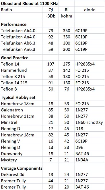 My database on radio Tank load resistance for maximum power transfer to the audio circuit.
Following I give the measurement conditions and input data for the above charts.
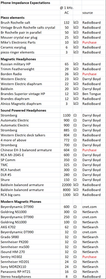 A web-based database on headphone impedance for various types of phones commonly used with crystal sets.
Phones I personally own and use are indicated in red.
kjs 2018