My Teflon Warrior
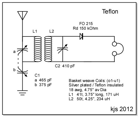
With this current radio I am making my entry into the "Performance Radio" constructors club. I have tried to follow all the best practices of high-end crystal set design while giving the set my own personal breadboard mark. Two central themes guided my design on this set, simplicity and simplicity. From the circuit diagram below you will note that I have chosen, not surprisingly, a simple double-tuned circuit layout with a Tuggle front end and a Tank/Detector circuit with no circuit decorations whatsoever. No taps. No selectivity enhancement. No Benny. No Decoration. No nada. This is a basic radio wherein I have striven to keep losses, including insertion losses, to an absolute minimum. Should I wish to include selectivity enhancement and/or benny at a later time, they will go on an outboard platform along with transformer and phone plug. The radio itself is simplicity realized.
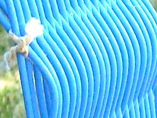
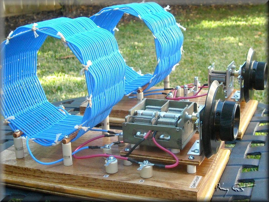
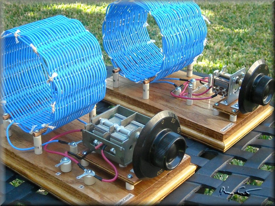
 As can be seen in the set photos below, this design follows standard practice of placing the open and closed circuits of the set on separate baseboards. This is important as it allows easy and wide adjustment of the coupling between the coils. With high-efficiency coils, very loose coupling is permitted with acceptable power levels, thus allowing very narrow bandwidths to be achieved. This can only be accomplished with separate base boards. To further minimize losses I have used short direct lengths of large 16 AWG stranded copper hookup wire and importantly, I have insulated all components and electrical connections from the board with ceramic standoffs. Finally, for the coils I have utilized a very lovely sky-blue teflon-insulated, silver plated wire of 18 AWG, strictly military spec, ($$$). I know, I KNOW.. This isn's a Litz Blitz set and yes, the performance suffers a little because of this. Still, I have good performance measures to tell me I am certainly on the right path. Note also that wire of such size and insulation is quite thick and to get the desired inductance required very large coils of some 4 3/4 inch diameter. The coils dominate the set visually and provide the name.
The tuning capacitors I would allow are most likely the weakeast link in the chain. I have chosen fairly generic though not bad-quality caps. The antenna tuner has a dual-gang cap with sections 465pF and 375pF respectively, well matched for my needs. Note, from my studies of antenna tuning (elsewhere on my pages) I have noted that a tuggle tuner does not necessarily require equal-size sections on the tuning cap. In fact, I would state that tracking is better if the ground section max's out at a lower capacitance that the tank section. The cap has aluminum blades and ceramic insulation and is a decent capacitor. For the tuning tank I chose a standard 410pF single gang unit from the Crystal Set Society. These are aluminum blade caps with phenolic insulation, OK but not superb. Both tank and atu include 3:1 reduction gears to help spread the band and allow more careful tuning. I did not allow for hand capacitance which I have noted is indeed a problem. When I tune the set to resonance with a signal generator, I find I am from 4 to 7 or more khz off peak tuning when I remove my hand from the dial. The set is fairly modular and readily modified so I am keeping my eyes open for better quality caps. I am afraid I must learn to live with hand capacitance. Oh well, we see about the next set!
Portrait of set, ummmm..

Performance summary:
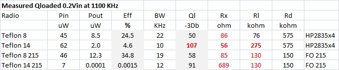
As mentionned at the start of the article, this set was designed as a high-performance rig. Lets take a look at the numbers and assess how well I did. On the spreadsheet above I have indicated the essential measures of the set in four configurations, two spacing tests (8 inches and 14 inches) with 4 parallel HP 5082-2835 diodes and two spacing tests with the holy grail FO-215 diode. First an explanation of the units:
Pin = Power into the set in microwatts
Pout = Power out the back end (into the phones) also in microwatts
Eff = Set efficiency or Sensitivity and is the ratio on Pout to Pin * 100
BW = -3dB Bandwidth of the set at 1100khz (f res)
QL = Loaded Q of the set = f res / BW
Rx = Input resistance of the set in ohms
Rl = Load resistance on the tank in kohms
Rd = Junction resistance of the diode in the set
The power numbers are fairly straight forward and represent the power calculated across the dummy antenna resistor and load resitor. Input to the set is from a signal generator with a 200mVpp signal output. Losses due to the dummy were accounted for and the input power is that presented to the set itself. Looking at the Efficiency and QL numbers one sees nicely the tradoff between sensitivity and selectivity. The larger the spacing between the sets, the higher the QL, but at a sacrifice of sensitivity. While the numbers look low, they are still good for crystal sets and the 107 QL is a superlative number. By comparison, I have looked at a High-Performance built by Dave Schmarder (see my Radio Test page) with big Litz and super capicitors and this set max's out around QL = 120-125. I would opine that any QL above 100 is "Performance Quality".
Note for a bit the Rx numbers. Impedance matching for maximum power transfer starts at the antenna and antenna tuner. The dummy antenna used for the measurements mimics a fairly typical longwire with an output impedance between 25 and 50 ohms. Of the many radios I have measured, most have set input resistances between 100 and 250 or so ohms. The tuggle tuner on this set is in the 50-80 ohm range giving an excellent match and maximum power transfer to the tank.
At the back end things get more complicated, a diode is present! For my testing I have included a step to determine, under test conditions of course, the optimum load resistance for maximum power transfer to the phones. Maximum power output means that the load resistance matches the output resistance of the tank/diode combination. The principal factors which influence this include the frequency and tank coil Q (which don't change from test to test), the diode Rd and characteristic, and the signal voltage being rectified.
Signal level and diode characteristic are inter-related and together determine the resistance of rectification. At very low signal voltages rectification takes place on the "square-law" portion of the diode with large swings in resistance with signal sine wave. Larger signal levels rectify higher on the characteristic curve (peak-detection region) with consequant lower resistances and less variation. The Rl shown on my table thus is specific for my test. My radio signal is in the 6-8 mV region placing it in the peak-detection portion of HP5082-2835 diode and possibly borderline square-law / peak detection on the FO-215. This explains why the optimum Rl is lower that of the HP but pretty close to the FO-215. It may also help explain why the FO bottomed out on the 14-inch separation, there was just no longer much signal for it to work with.
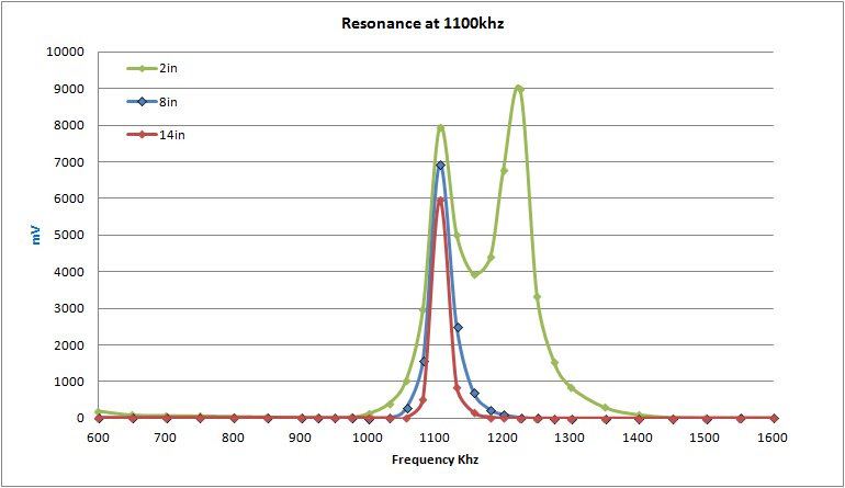
A look at the resonance curves above (including an over-coupled 2-inch spacing case) is very interesting. I include this as a nice demonstration of resonance at various conditions of coupling. The 2-inch coupling case clearly demonstrates the problem of over-coupling in a radio. Two resonance peaks show up and tuning brings in different stations at the same time. Total power is still very high, just not useful. The 8-inch case is pretty close to critical with good power and the two-peak problem eliminated. Bandwith is still pretty high at 22khz (the curves are made with the 4 parallel HP's). Finally when separated to 14 inches the power loss is not too bad and bandwidth has narrowed to 10 giving a loaded Q of 107 as mentionned above.
It ain't Litz, but PD Close!
kjs 11/2012