A Telefunken (aka Mystery) Set
My first homebrew crystal set was a Mystery set based on the 1932 Brisbane design. I was rather very inexperienced and my set turned out very poor indeed. Subsequent mods helped improve it somewhat, at least allowed it to tune much of the broadcast band. Still, its sensitivity was poor and selectivity pretty much non-existant. Well, it looked nice.
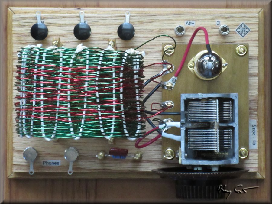
I have learned much in the several years that have followed and have been feeling it may be time to revisit the old Mystery design. The design in fact is based on an older German design concept by Telefunkun Corp, so that is how I choose to refer to the set now. I have basically settled on Mike Tuggle's incarnation with an antenna connection available on either the primary or secondary coil as desired. Also like Mike's set, the coil is a co-would basket weave over one and under two. From there the resemblance to Mike's set stops.
Given the single-tuned design this will not be a performance set and I have gone with 18awg magnet wire for the coil. The coil is bifilar co-wound with 3.7" ID and 4.1" OD. The Open Circuit Coil has 58 turns and a length of 2.8 inches. At 1.0MHz the inductance is 229 uH and has an unloaded Q of 260. Rp = 390 kOhm. The Closed Circuit Coil has 30 turns and is 1.7 inches long. At 1.1 MHz the inductance is 76 uH with an unloaded Q of 175. Rp = 90 kOhm. The Open circuit coil is Tuggle tuned with an older Russian 2-gang 450 pF variable cap with a 3:1 reduction gear.
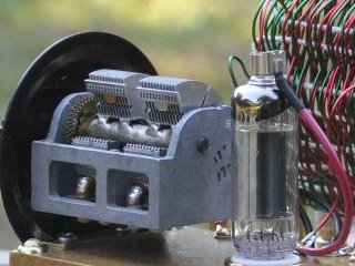
For this set I have chosen to include a single vacuum tube for the detector with no provision to switch in solid state diodes. I was tired of being lazy with my Fleming set and just using the diode. This set uses a Russian high perveance 6C19P vacuum diode giving good sensitivity. Additionally I included a Benny in the detector circuit for purposes of measurement and possible small improvement in selectivity, who knows? What I can say is that, when I short across the benny I get an immediate reduction in volume/sensitivity. So, it must be doing some good.
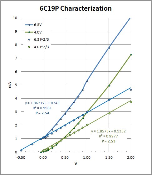 The graph at left shows the I/V characteristic measured for the 6C19P diode. I include measurements at two heater voltages, 6.3 (operating spec) and 4.0 volts. Additionally I show the currents raised to the 2/3 power. Current to the 2/3 power gives a linear relation with voltage in each case and was first noted by Langmuir and Childs, now refered to the Langmuir-Childs Law. The slope of the curve returned to the 3/2 power results in a number called perveance and is a measure of the efficiency of the diode for detection. It is also seen for the curve at 6.3 volts that there is substantial positive current even at negative bias on the plate, out past -0.5V. This "Contact Potential" is death to rectification and by reducing the heater voltage one may reduce the potential to near zero thus maximizing the diode sensitivity. The perveance is only minimally impacted.
The operation of the radio is intended with 3.9 to 4.0 Volts on the heater for best performance. The tube is a power hog and will not run off a battery. Current draw at spec 6.3V is 1.2 Amps! Even at 4.0V it draws 0.8A. You better have a power supply. Still, the power runs the heater only, the set remains non-amplified.
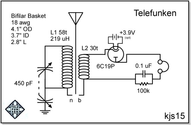
Schematic:

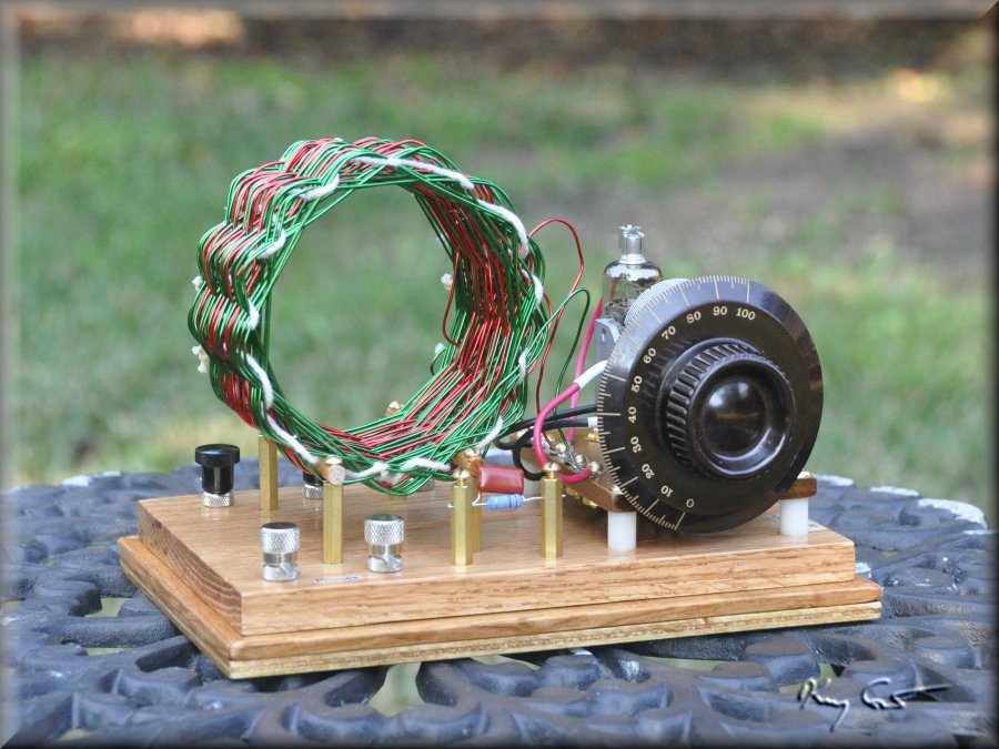
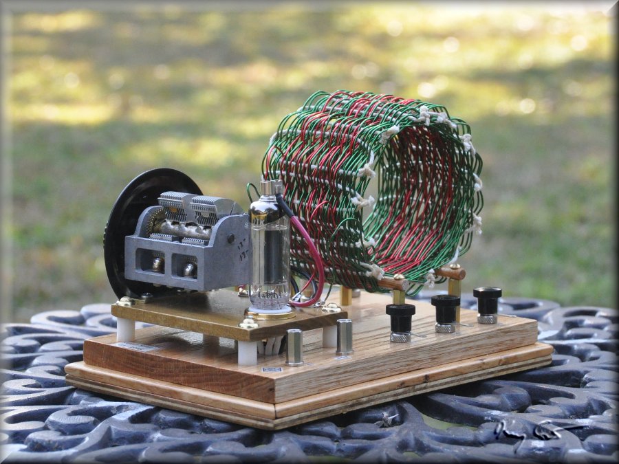
Portraits of the set:
Performance Testing
I have completed several tests on the Telefunken Set with its 6C19P vacuum detector. It passes surprisingly well, better than I had thought but with some reservations.
While I tested the set at both 6.3V and 4.0V heater voltages, the results were not significant and here I present only the results from the 4.0V heater.
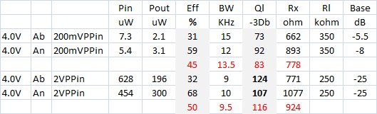
The set has two antenna connections, a "n" (narrow) band connection to the large tuned coil, and a "b" (broad) band connection to the smaller detector coil. On narrow the set has an imput resistance Rx from 0.9 to 1.1 kohms. On broad Rx ranges from 0.7 to 0.8 kohms.
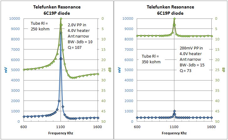
Testing with a 2V PP input signal (Local station simulation) the set Q is over 100 which I find remarkable for a tube detector. Load resistance for maximum power (presumably equal to the tube Rd) is 250 kohms and all tests were made with this load.
Testing with a 200mV PP input signal (DX simulation) the set Q is lower at 80 +-, still quite pleasing. Load resistance is higher at 350 kohms and the 200mV tests were run at that load.
One critical observation I have concerns the resonance "floor" of the set. Looking at the resonance curves, tuning the band out of resonance floors out at about -25dB with the 2.0V input, and only a platry -7 dB with 200mV input. As a comparison, I looked at a double-tuned set with good Q and the resonance floor was closer to -50 dB or so. The reason for this has to do with the vacuum diode which may allow a small current to flow through the circuit depending on the plate temperature. In practice one wishes to adjust the heater voltage to a temperature where a small current "only just" starts to flow, still maintaining good sensitivity to received signals. (More on this van be found in my Diode III section under Radio Labortory). In my testing I have used 4.0 V on the heater, still a bit too warm and so, the shallow Db floor to the results shown below.
Anyway, the set behaves remarkably well, better than I had expected. With its Q over 100 and proper heater adjustment this set should outperform most one-dial crystal/diode sets out there!
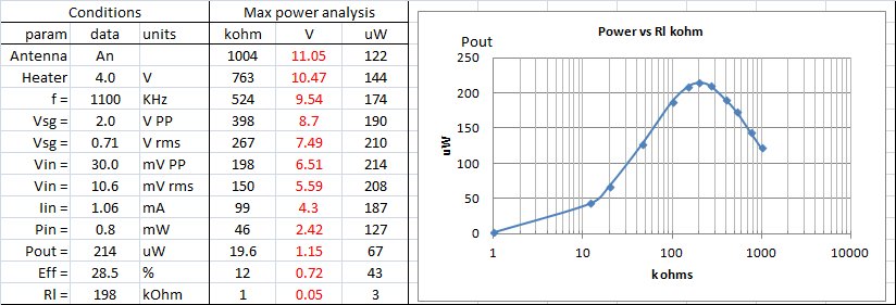
More interesting measurements on the set, telling me how the tube is doing.
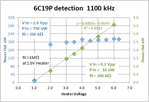
Above we see no relation between matched output power and the tube heater voltage at 20mV input (2.0Vpp on signal generator), and a monotonic increase in output power at 6mV input (0.2Vpp on the generator). I can hear a peak output power at around 4.0V on the heater, but do not see this on the chart.
Two significant observations follow: A) At 2.0Vpp on the generator there is little loss in sensitivity down to about 2V heater voltage and: B) At 200mV generator input the set sensitivity decreases monotonically with decreasing heater voltage.
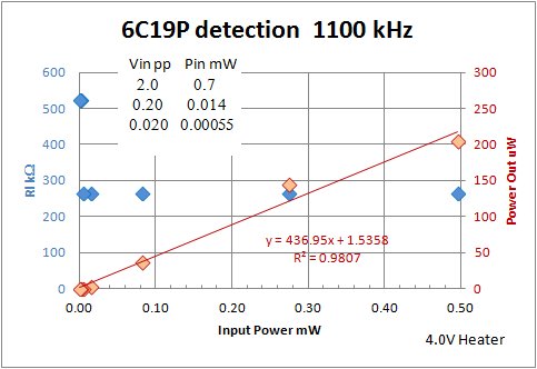
Input power relates linearly to output power suggesting a constant set sensitivity, and I find the matched output load also remains constant. Unexpected, but I had no real expectations really.
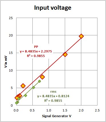
Just to be thorough I take a look at the input voltage to the set versus the voltage delivered by the signal generator. The dummy antenna is pretty lossy with 2Vpp from the generator translating to just 20mVpp getting into the set. Looking at the generator set to 200mV, the signal into the set is a paltry 5mV. Because of my lossy dummy antenna, I am in fact measuring at far lower input signal levels than the signal generator setting indicates. Results from my 2.0Vpp generator setting may be more relevant to DX than I have previously suggested.