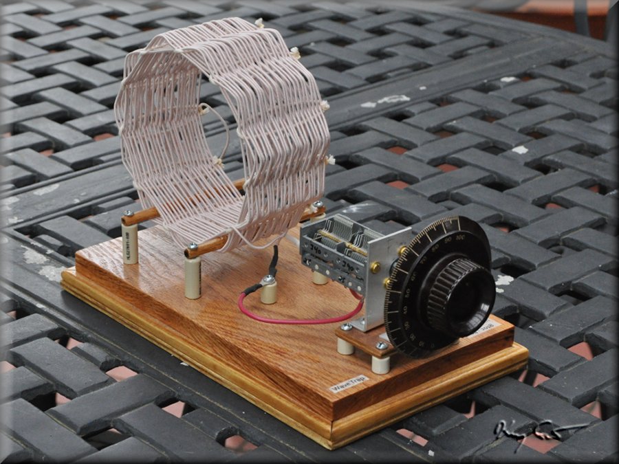
Here I present an inductively coupled trap that I built to be used with my Big Litz set. This coil shares the same diameter and construction as my main set tuning and antenna coils. With this big boy I can tune to the offending signal and trap it very effectively. I have measured and modeled each component of the trap separately, and I have measured the performance of the assembled trap as well. All this permits me to compare the modeled, or expected performance to the actual performance. The goal is to build a high-Q trap with a deep narrow notch in order to trap out strong local signals and dig out nearby DX.
In making Q measurements on any component (Capacitor or coil), one must have one component calibrated and measure the tank Q itself. From the tank Q and calibrated component Q, it is straightforward to mathematically extract the Q of the component under test. I also wish to know the trap Q across the entire MW spectrum as it is not a constant value. In the following discussions then, I will present diagrams with the measured tank Q, calibrated component Q, and extracted component Q versus frequency. I also present the measurements with a model of the expected trap Q versus frequency and the actual measured Q versus frequency. Finally I give the resonance and phase measurements at a frequency of 1100 kHz.
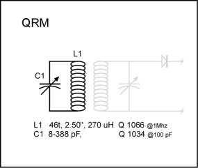
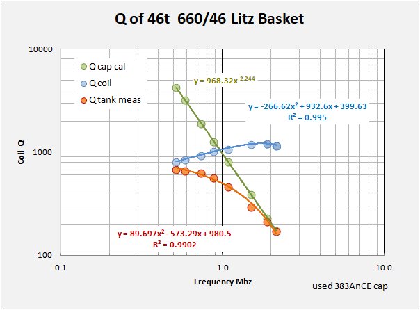 An inductively-coupled wave trap is a fairly simple device consisting of a single tank, One variable capacitor and one coil. For my trap I have wound a basketweave of 5 inches diameter with 46 turns of 660/46 litz wire for low skin and low resistivity. The chart at left shows my measurements and Q calibration for the coil. Green points indicate my calibrated capacitor and the orange points are my measurements on the tank. From those I have ectracted the coil Q across the MW band. Q = 1100 at 1 MHz, just what you expect from big litz.
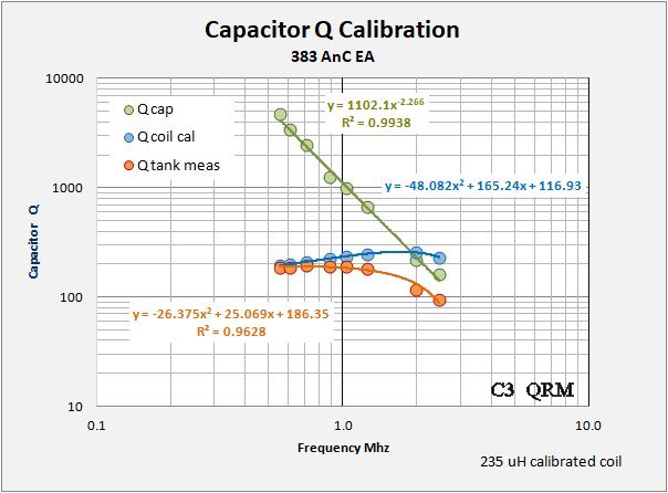 The variable cap is an eastern European affair I found on eBay. It is, or should be, about as good a cap as I can lay my hands on, but far from the holy grail. Again, the chart at left shows the calibration. This time the blue points are from my calibrated coil and the orange points are the tank measurements. From those I extract the cap Q across the MW band for my trap. About 1100 Q at 1 MHz. For a variable capacitor that is a disappointingly poor result, similar caps generally give significantlly higher Q's. It is no wonder I have used this cap with the trap and not in the main tuning circuits of my Big Litz set!
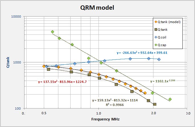 From those component measurements above I can now model the expected trap performance and compare that with the measured values. The chart at left shows the extracted MW Q's for the coil and cap (blue and green points) used in the tank along with the modeled tank Q in orange. The brown squares show the actual tank Q measurements. The results are similar with the measured values being somewhat lower that modeled. This is to be expected as there are other sources of resistive losses in any build. Overall I am disappointed with the poor cap which results in the wave trap having an overall low Q, only 490 ar 1.1 MHz.
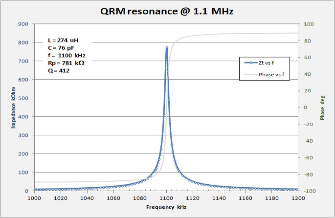 Finally I have measured the tank resonance at 1100 kHz. At -3dB I calculate a tank Q = 412, close to my ring-down measurements, within measurement error. This is still a very sharp notch and the trap should function well for its intended purpose.