When I first began researching this project I was surprised by the difficulty in finding useful technical specifications for ignition coils of various manufacture, or even of knowing what constituted a "good" versus a "bad" spec when such specs were found. What little information is generally published includes the maximum voltage naturally, often the secondary resistance, sometimes the primary resistance and the turns ratio, (ratio of primary to secondary windings). At first look there doesnĺt seem to be much correlation between voltage and turns ratio or even resistances. It took a lot of research to learn the needed theory behind Kettering ignition coils and much of what is found on the web is inadequate, oversimplified, poorly founded theoretically, or downright wrong. I will try here to explain in moderate detail how the Kettering Ignition System works, the theory, and therefore how the various components (windings, primary, secondary, capacitor, resistances, etc) work together. With the right theoretical underpinnings, the specs do make a lot of sense.
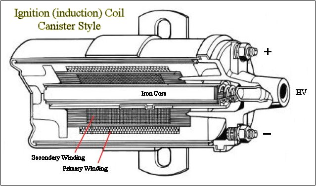
Induction coils operate by storing large amounts of energy in the form of strong magnetic fields. As currents pass through the windings their electric fields generate magnetic fields, and fields in one coil induce fields in the other, primary and secondary. As long as a current is maintained in one winding its magnetic field is sustained and a corresponding field is sustained in the second winding. Conversely, moving the coil through a magnetic field or removing the field entirely will generate an electric field, (measured as voltage) in the coil. The ratio of turns between the windings determines the ratio of voltages between the coils. Although the input voltage to the primary coil is small, only 12V for a car battery, it has a large current and a great deal of magnetic energy will be stored in the primary coil. By shutting off the primary voltage source the magnetic field of the primary collapses. As this magnetic field collapses it cuts the secondary coil generating a very high voltage output. The rate of field collapse (dB/dt) determines the strength of the voltage output of the secondary. This high voltage output spikes only when the primary current is shut off causing the field collapse. Coils therefore require an interrupter to repeatedly switch the current to the primary on and off. The trick is to select materials with needed properties to achieve the results wanted. The Kettering Ignition system use in this project is described next.
The Kettering ignition system consists of a 12v battery (the source of emf), an induction coil, a capacitor, and a switch of some sort, (points, relay, vibrator etc..) in a car its points. For the coil the primary and secondary are wound in series and connected together inside the canister. The coil has inductance and impedance/resistance. As the system has LRC, (L = Inductance, R = Resistance, C = Capacitance) the circuit has a resonant frequency and this frequency determines the unit time period "dt" in the equation V = L di/dt. Even without the capacitor there remains some distributed capacitance in the coil and so opening the points will never instantaneously collapse the magnetic field, but it will be extremely fast just the same. The field is maintained by the current from the battery to ground, opening the points removes the ground and stops the current.
As the circuit has a more or less fixed L and R from whatever coil you have available, you can only vary C by choosing the capacitor carefully. For cars, this typically means a capacitance in the 0.1 to 0.2uF range. This capacitance gives a resonant frequency such that the dt will deliver a 30kv jolt to the plugs from the secondary of the coil within the period allowed by the engine timing.
A smaller dt (shorter unit time) delivers a higher secondary V (do the math) but standard coils are not designed for this and the internal insulation will probably not handle the tension. Additionally, the primary also delivers a voltage back to the switch/points/relay. A smaller dt will also result in a higher V off the primary. Of more importance, the smaller dt means that the back emf hits the points early before they have had much time to open. Either the higher V and/or the early arrival will cause arcing at the points. Arcing at the points creates a low resistivity path to ground and leaks the power away from the coil and so the secondary will also not deliver much V to the gap.
Conversely, a dt too long will slow the rate of charging and prevent the coil from being charged sufficiently in the time available (dwell time). The field collapse will be slower lowering the voltage out of the secondary, V = L di/dt. A smaller capacitance means higher frequency/smaller dt and vice versa.
As dt is determined by the resonance of the LRC circuit, the variable you have to work with is generally the choice of capacitor value. Modern high performance coils also factor in. they have lower R (resistance) and lower L (inductance). lower L hurts because the energy stored in the coil is as follows: Energy = 1/2 LI^2. Reducing L lowers the stored energy. lower current (I) also lowers stored energy. Lower R increases the amount of current flow per unit time as well as increasing the frequency of the resonant circuit. Larger di and smaller dt means a much larger V. High performance coils are designed to deliver 45kv instead of 30kv and must have the insulation appropriate to this. The "performance" of these coils comes from two favorable factors, the high voltage assures sparking in high compression and the small dt allows sparking at high RPM's in 8 cylinder engines. That is, itĺs the small dt that allows sparking at very fast cycle times. They still have roughly 100:1 turns ratio.
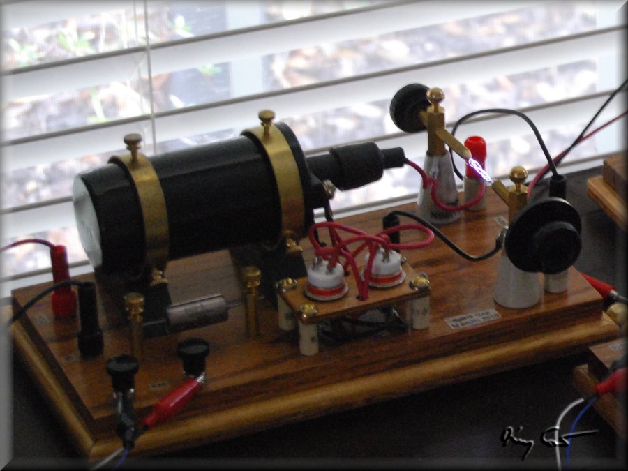
Photo of the induction coil / ignition coil mounted horizontally on the power breadboard. Other components seen include the interrupter relays, the capacitor used to determine the coil resonant frequency, and the active spark gap. The thing really works!
The following are a few easy specs on some popular ignition coils, only a small sampling:
PerTronix 45011: V max = 45000 V, P res = 0.6 ohm, S res = 8.6 ohm, P ind = 5.5 mH
Mallory 29217: V max = 58000 V, P res = 1.4 ohm, S res = 10.0 ohm, P ind = 6.6 mH
MSD 8202: V max = 45000 V, P res = 0.7 ohm, S res = 5.2 ohm, P ind = 8.0 mH
Taylor 718203: V max = 45000 V, P res = 0.7 ohm, S res = 4.7 ohm, P ind = 8.0 mH
For my project I have used the PerTronix coil above although I imagine most will do nicely. The Kettering discussion, appropriately placed here in the Induction Coil write-up, is needed understanding in the next section on the Coil Interrupter selection.
