A Spark-Gap Transmitter
Why a spark-gap transmitter? And why here on a crystal radio page? Well, the second question I'll answer first as it is easiest. The transmitter is a vintage technology device that is no longer current in the modern world and so fits thematically with the purpose of my crystal radio page. The first Question is more interesting, why build it? In late 2009 my elder brother, founder and owner of Northwest Research Engineering, LLC., in Seattle, challenged me to construct a spark-gap transmitter. He enjoyed seeing my vintage-style crystal sets and we enjoyed discussing the early history of radio together. So, it seemed a logical step to progress in this direction. Additionally, as his work is in cutting edge ionospheric research, he has little opportunity to study such retro technologies up close and personal.
DISCLAIMER:
I am not a licensed radio-amateur and in any case a spark-gap transmitter is not legal to use in the United States. As such, this project was taken on as a technology-demonstration exercise only and is not intended for actual use. Such use is not permitted. Nor is this page intended to promote the construction and use of such transmitters by others. I DO give detail on the construction and theory of the transmitter in order to better understand and appreciate the technologies used at the dawn of the modern wireless era.
The concept behind the project is to build an operating spark-gap transmitter using technology as close as possible to that used at the turn of the 20th century. Technology that would be recognizable to Marconi or Fleming. This meant no chips, no transistors, no diodes, (OK, a galena and cat's whisker is technically a diode, but you know what I mean...) no solid-state. It does not mean using vintage components as these are for the most part unobtainable and/or prohibitively expensive. With each component new or homebrew the question is: would Fleming recognize this? Sometimes I needed to stretch things somewhat, especially concerning the relays, but still I believe I have remained true to this original goal.
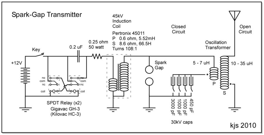
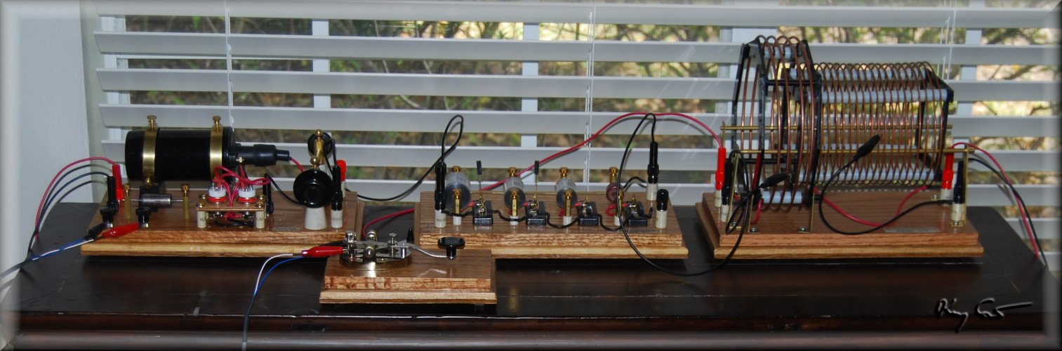
The transmitter was conceived as two modules, a power module and an oscillation module. Size constraints forced me to break the oscillation module further into two breadboards, one for the variable HV capacitance and the other for the oscillation transformer. The power module is the most complex piece having on it the induction coil, interrupter, capacitor, and the spark gap itself. To keep this page length manageable and allow enough space to give a good description of each component, its theory and function, I have broken the descriptions into separate links below.
INDUCTION COIL..
COIL INTERRUPTOR..
SPARK GAP..
OSCILLATION CIRCUITS..
PERFORMANCE TESTING..
The following circuit diagram and photo shows the complete transmitter and how the modules integrate together: