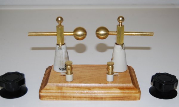
Early use of the spark gap, especially with a weak induction coil, showed up room for improvement. When sparking the brass balls build up an oxidation layer fairly quickly. This layer increases the dielectric between them and, especially when the voltage is marginal, (my first coil was old) the sparks had trouble to jump the gap. I needed to clean the balls frequently with steel wool. The 1/2" balls spread out the field flux over a small area. One improvement was to switch from a ball-gap to a gap between sharply pointed tips. The photos below show both configurations. The points concentrate the field creating a higher energy density. This makes it easier for the sparks to form. Switching between configurations is as easy as screwing on or off the balls which cover the pointed tips.
Adjustment of the gap length is easily accomplished by turning the end knobs of the threaded supports. Small top thumb-screws lock the posts at the desired position. CAUTION: Do NOT touch any metal components while the spark gap is in operation. Handle by the insulated knobs only.
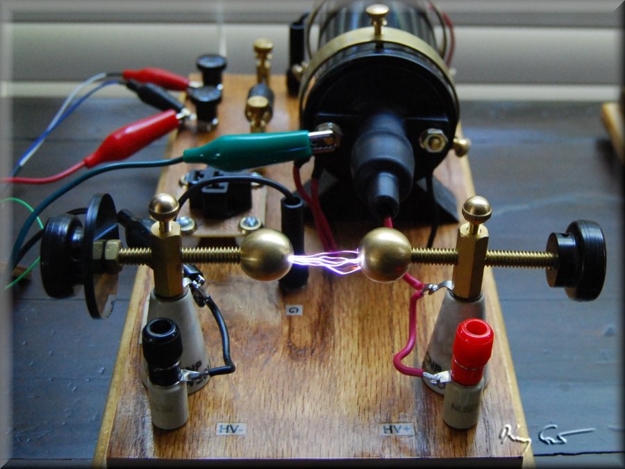
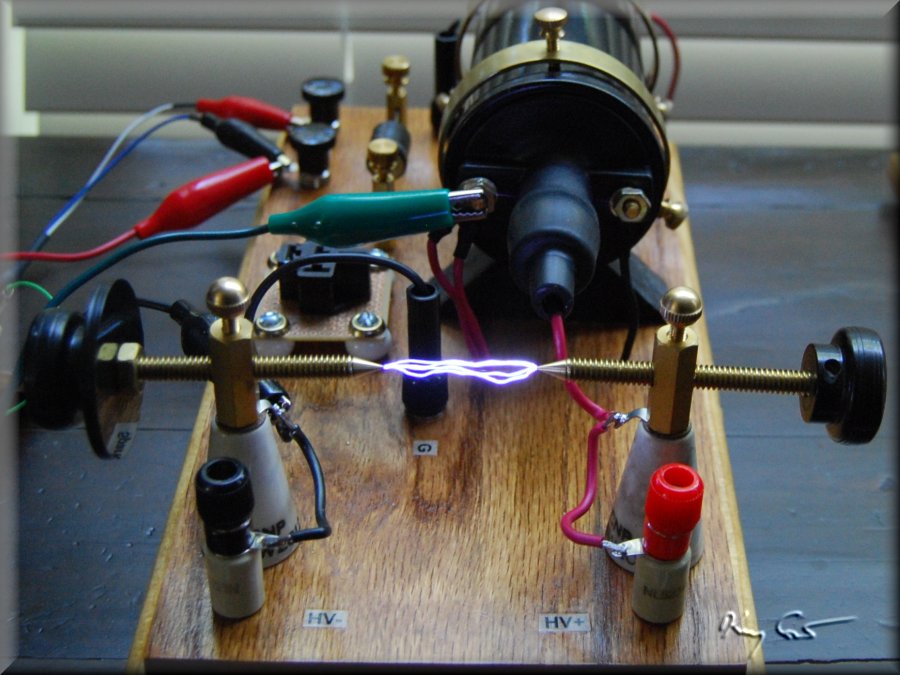
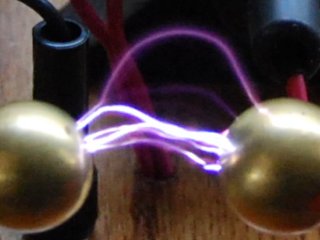
In the photos above the sparks are being produced without any ballast resistance and are just over 2cm long. With the ballast I subsequently added to protect the vacuum relays, the spark power is lowered from 20 amps down to about 14 amps. The sparks obtained are smaller, about 1 to 1.5 cm. According to Fleming an induction coil capable of producing sparks up to 10 inches (25cm) in air will give a spark of 6-7 mm when connected to a load. I find with the tank circuit connected to the gap I need adjust the spark points very carefully and close, about half a mm or less to obtain consistant sparks. This can be a frustrating exercise. Air diaelectrics also have the problem of arcing when the air between the electrodes begins to ionize. A solution to this is to enclose the spark gap in a vacuum. It just so happens that occasional inexpensive vacuum spark gaps are listed on ebay. These tubes are intended for radar (UHF) applications and are rated in the few hundred volts range. As my gap is tiny now, I felt this may be a good solution, or, alternatively I might have some fun blowing up a cool vacuum gap. The following photo shows that in fact the vacuum gap performs handsomely as a gap for my transmitter. The gap length is mercifully fixed at about a half mm and the low diaelectric allows good sparking with flat (rather than pointed) spark surfaces about 2mm in diameter. I certainly will experiment more with this kind of gap.

Thats'a some glow...!
**********
OTHER SPARKS:
Of note, the gap itself need not remain strictly a set of pointed, flat, and/or round surfaces. Once you have a working High Voltage power supply, there are other gaps/toys waiting to be tried.
The photo below is a quick cobbled together Jacob's Ladder just to see: Will it work? The copper wire is not perfectly smooth nor can one adjust the spacing between the two verticals. Still, I can tell this will be a fun side trip with my HV power supply. Stay tuned for more.
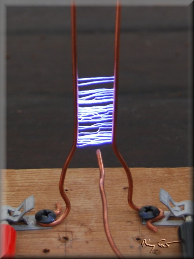
Schazzam!!
