Performance Testing the Transmitter
If you build it, will it work? And how well? This page attempts in a preliminary manner to answer these questions and provide a first look at the performance through the eyes of an oscilloscope. It will take much testing and observation/head scratching before I ferret out all the phenomena present in the set. This is one of the objectives of the project, to study and learn about spark-gap technology. The plots below are a first look, some will raise more questions than answers, but that’s the fun!
All of the scope plots presented here are made with a single hookup to the scope. The scope probe was attached to the set antenna output of the oscillation secondary coil.
Many other observation points remain to be made and observed and I will update this page accordingly when needed. I present observations of the three primary oscillation frequencies expected from the set: A) the pulse frequency from the relay, B) the resonant frequency of the induction coil + power capacitor, and C) radio frequency oscillations of the transmitter itself. So little work so far, so many questions remain!
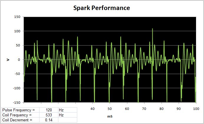
This first plot above shows the response at audio frequency. In the 100 mS plotted we see 11 pulses at 120 Hz frequency. This represents the pulse frequency of the dual relay system, two relays at a nominal 240 Hz each. Each pulse starts with a high amplitude spike associated with the spark discharge and followed by two to three damped oscillations with a frequency of 533 Hz. This oscillation is associated with the natural frequency of the induction coil itself. Damping of waves is a natural oscillation feature and is refered to as the wave Decrement. Decrement is the natural log (Log to the base e) of the amplitudes of any two successive peaks in the wave train. It results from the loss of energy in the circuit during the oscillation period. Energy is lost due to resistive heating, radiation of waved into space, and interference between oscillations in the primary and secondary oscillation circuits, especially where they are closely coupled. Where resonance is high the interference losses are minimized.
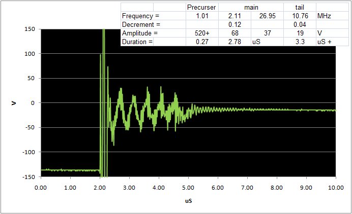
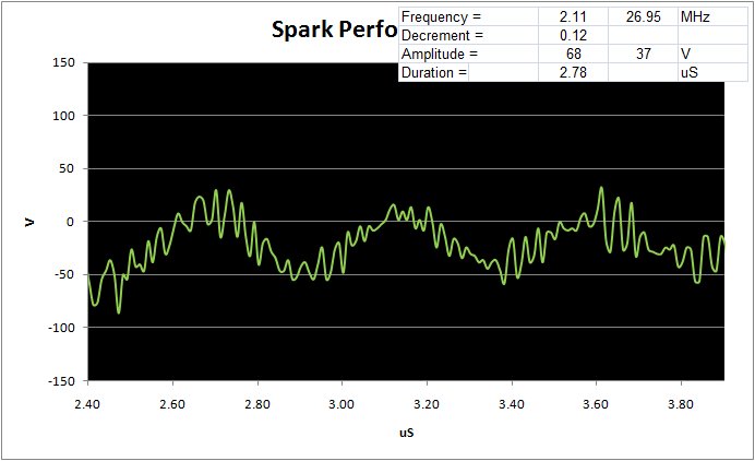
Zooming in to the radio frequency world the above plot shows the radio frequency wave in some considerable detail. This plot indicates that the oscillations given off from a spark gap are anything but pretty. The complexity results from the ringing going through several phases with the closed and open circuits, and induction coil each having their imprint. The initial (precursor) phase of the event, lasting here about 0.27 uS is the high-amplitude energy (upwards of 520+ V) of the spark as the induction coil pours its energy directly into the circuit at the gap. This is followed by the main phase, a complex 68 V amplitude ringing lasting some 2.8 uS. The ringing consists of two combined waveforms, one, a high amplitude (68 V) 2.11 MHz wave with a second lower amplitude (37 V) high frequency 27 MHz wave superimposed. This phase results while the closed (primary) circuit still retains sufficient energy to cause sparks at the gap with each main oscillation. The higher frequency wave comes from the open circuit (secondary) inductively coupling to the closed. A detail look at the main phase seen below:
Finally, when the energy loss finally quenches the sparking at the gap, the open, secondary circuit then can freely oscillate, here with a frequency of 10.76 MHz and lasting some 3.3 uS. This last phase is the desired transmission frequency and the open circuit normally oscillates into the antenna. Decrement on this last phase is an excellent 0.04. Early spark gap transmitters struggled to reduce or eliminate the initial two phases of the event with quenched gaps.
Why is decrement important? Most RF damping in a spark-gap transmitter results from interference between oscillations in the open and closed circuits of the oscillation transformer. When these waves interfere two separate wave energy peaks are radiated from the antenna causing loss of signal strength at the desired frequency and adjacent channel interference. A good spark-gap transmitter should quench the closed circuit as quickly as possible after the energy is transferred to the open antenna circuit. Once quenched the open antenna can resonate at its natural frequency. Lacking quenching as with my transmitter, the oscillation transformer needs to be carefully tuned to resonance and loosely coupled to radiate at a single frequency. High decrements, (in the 1920's a spark-gap transmitter was required by law to keep a decrement of 0.2 or below) indicate a poorly engineered / poorly operated station. Calculations for the wave decrement as follows:
Decrement = 1/n ln (Xo/Xn) where Xo is the amplitude of one wave and Xn is the amplitude of another wave n periods following.
Damping Ratio = 1/sqrt(1+(2pi/D)^2) where pi = 3.14 and D is the decrement from above.
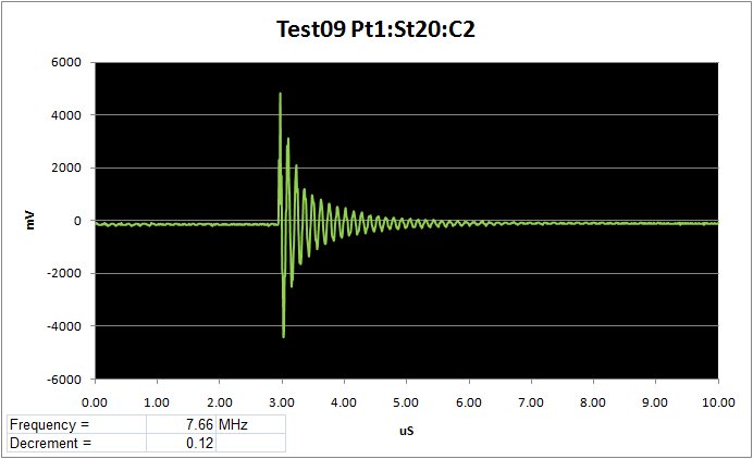
A particularly nice example of an isolated fully-quenched oscillation follows. I assume in this event that enough energy remained present in the closed circuit to allow an occasional isolated single spark to jump the gap. Such a spark produces a nice ring in the open circuit without the complexity associated with the main sparking from the induction coil. This plot shows the open circuit ringing nicely at 7.66 MHz frequency with an acceptable 0.12 decrement.
Right about now the observant reader must have noted that the frequencies measured, 2.11 MHz on the closed circuit, and 7.66 MHz on the open circuit, (and variations in-between) do not compare well with the design frequency desired. This certainly needs to be looked at. Recall my original design was for 2.5 MHz on both circuits with the following parameters:
Closed circuit:
Primary coil = 2 uH
Capacitance = 2000 pF
Wavelength = 1884 * sqrt(L*C) = 119m = 2.52 MHz
Open circuit:
Secondary coil = 20 uH (L1)
Distributed inductance = 20 uH (Lo) La=Lo/3 = 6.65 uH
Distributed capacitance = 150 pF (Co)
Wavelength = 59.6 sqrt((L1 + La)*Co) = 121m = 2.48 MHz
Wavelength = 1884 * sqrt(L*C) = 121m = 2.49 MHz
Under testing conditions I have made some significant changes to the above. Specifically, the lumped inductance and capacitance are changed to P = 6.2uH (closed circuit), S = 17.4uH (open circuit), and the capacitance = 1070pF (closed circuit). Also, the design assumed a "generic" antenna with distributed values La = 6.65uH and Co = 154pF. Under test there is no antenna and the scope probe gives about 25pF capacitance and no inductance. Substituting the test values provides the following analysis:
Closed circuit:
Primary coil = 6.2 uH
Capacitance = 1070 pF
Wavelength = 1884 * sqrt(L*C) = 153m = 1.96 MHz
Open circuit:
Secondary coil = 17.4 uH (L1)
Distributed inductance = 0 uH (Lo) (no distributed inductance)
Distributed capacitance = 25 pF (Co) (Scope probe in X10 position)
Wavelength = 59.6 sqrt((L1 + La)*Co)
Wavelength = 39m = 7.63 MHz
The two following plots give spectral analyses of the oscillations in the closed and open circuits.
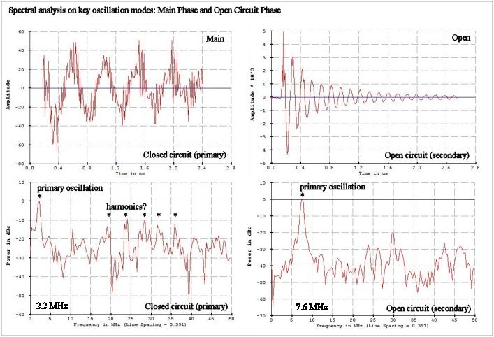
This analysis gives a pretty close prediction to the values actually found on the testing and gives confidance that things are behaving as per theory. Other frequencies noted are harmonics and/or interference between the open and closed circuits. The original design was set so that both open and closed circuits resonated together at 120m. Under test the two circuits have different wavelengths and so will set in motion a variety of unwanted harmonics. Presumably, with an actual antenna close to the design specs the transmitter will perform flawlessly!
*********
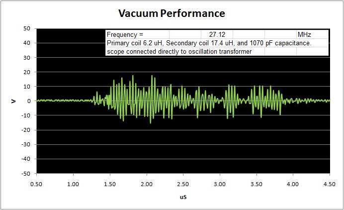
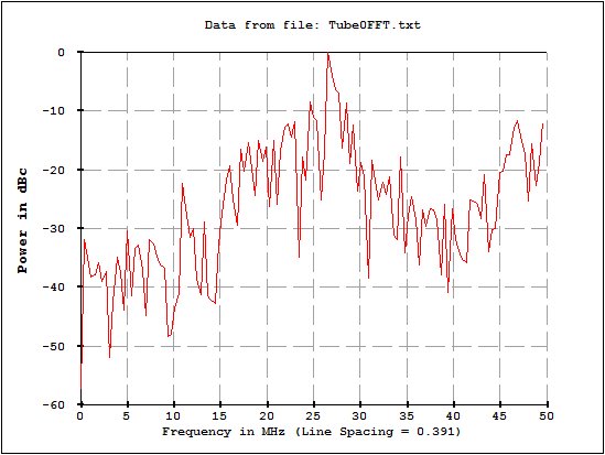
The above analyses are presented with the transmitter and gap working in their "normal" operation mode. You will recall in my section on the spark gap that I also have tested a UHF vacuum tube spark gap. The following plots give some early interesting results needing presentation here. The RF oscillogram is quite typical of what this spark produces. You will immediately notice that instead of an RF pulse consisting of several distinct phases as before, this gap produces very clean almost pure HF tones with varying amplitude in the 27MHz range. These two differences, unphased tone and high frequency need explaining. For the difference in frequency I am really at a theoretical loss, all the formula I have tell me that the frequency results from inductance and capacitance, two parameters that did not change. I can only speculate that, as the spark resistance ought to be significantly lower in the vacuum gap, this may be the cause. More testing and more reading needed!
As for the tone itself, again I need to speculate and hypothize. If you look again at the initial audio-frequency oscillogram, you note the obvious induction coil audio oscillations as well as the initial spark. Normally these oscillations should not be seen unless the electrodes are separated far enough to prevent sparking. Initially in my testing this was the case, but with time the coil oscillations became a normal part of my responce. Additionally, with time I have had to adjust the electrodes ever closer to get consistant sparking, thus the frustration. I hypothize that the electrodes themselves are getting quite oxidized. This results in an uneven and "messy" spark. More importantly, I suspect that there is a LOT of arcing taking place at the gap as well. Arcing is a continuing current that effectively shorts the closed circuit to ground. This would explain why the audio-frequency coil oscillations are present even when the sparking is present. The vacuum gap prevents oxidation and produces a clean spark with every pulse. The electrodes are also made of either zinc or tungston or some other refractory metal. The lesson to be learned, make your electrodes of something more durable than brass and get some steel wool to FREQUENTLY clean the tips!
If I can get my arms around the frequency and learn to control this, I see this as an excellent gap for my set. But, would Professor Fleming recognize this? I must fall back to my vacuum relay justification and restate that Fleming, as the inventor of the vacuum tube, was no stranger to placing elements inside a vacuum. He would certainly recognize this.
*********
Transmits:
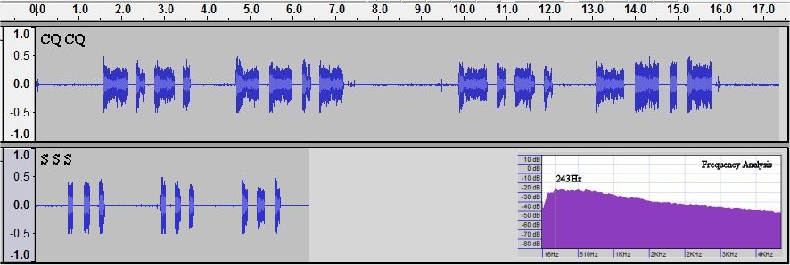
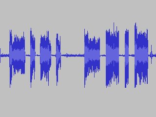
Does it work? What does it sound like on an AM radio? I recorded the above plot off a small AM radio tuned to the top of the broadcast band. Plenty of signal to go around, I understand why these transmitters are no longer allowed to operate! I give you a couple CQ's and an SSS in commemoration of Marconi's first transatlantic radio reception on December 12, 1901. Fleming designed the transmitter power station at Poldhu for the transmission.
CQCQ Yes... it really IS a transmitter..
SSS
73
