Coil Interrupter
In order to function properly an induction coil requires an interrupter circuit. The high-voltage output of the secondary winding results from the magnetic field collapse of the primary when its current source is interrupted. A single interruption will cause a single HV spike and thus a single spark. Repeated sparks require repeated charging and closings of the primary winding. For my project I was seeking a pulse-rate some 60Hz or better to give an audible tone at the receiver. Too rapid though and the induction coil will not have enough time to charge between cycles. Putting things into automotive terms, a 4-cylinder engine idling at 750 rpm must cycle the coil every 40mS, or 25Hz, no problem. For an 8-cylinder engine running at 2500 rpm you are down to 6 mS cycling (170Hz) and many coils are unable to work well at such rates. High performance coils are intended work well even at such high rates. For the transmitter I feel a cycle frequency between 60 and 100Hz would be ideal.
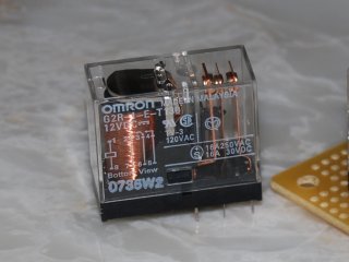
It would be lovely if cycle timing were the only constraint, general purpose relays typically run around 60Hz. Indeed this was my initial design, woe is me. Another concern the interrupter needs to deal with is the presence of a back emf from the induction coil primary winding. With a 100:1 turns ratio, a coil that sends a 45kV pulse out the secondary will also send back to the interrupter a 450V pulse. Small general purpose relay contactors remain rather close together even at their widest separation and so are prone to arcing with modest voltages. When I first hooked up my relay I got modest sparking from the gap and contact arcing that was quickly burning up the relay. It was my belief that the capacitor was there to slow the process and allow time for the relay contacts to separate before the back emf hit. I tried capacitors of increasingly high capacitance, they did not cure the problem. It was time to hit books and work the test bench.
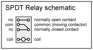 What follows was a better understanding of relays in general, and SPDT relays wired in a buzzer configuration in particular. An SPDT relay has a common contactor set between two posts. The contactor has a spring which keeps it in contact with one of the posts, the "Normally Closed" (NC) position. The other post thus represents the "Normally Open" (NO) position. The relay also contains a small coil that, when energized will push the contactor towards the NO position and so breaking the NC contact. In a buzzer configuration, breaking the NC contact also de-energizes the relay coil so there will be no more push towards the NO post. The contactor will use what little momentum it has to oppose the spring and move to the NO position. In reality this momentum is not sufficient and so no contact with the NO post is ever made. This is why one always uses the NC post with the SPDT buzzer relay. A further negative consequence of this is that the contactor never separates far from the NC post. The close proximity allows breakdown of the dielectric potential of the air between the posts and arcing to occur.
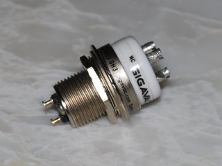
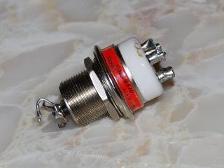
Solutions to this arcing problem come in two flavors, the dielectric and the contactor separation. One solution used in high power relays is to enclose the contactors in a high-dielectric oil to suppress arcing. This is very effective but the fluid is difficult to work with, expensive, and it slows the contact frequency greatly. Recall that I am seeking at least a 60Hz contact frequency. Another way is to place the contactors in a vacuum. While not as good a dielectric as oil, it is significantly better than air and has the advantages of being easy to work with and maintains high frequency operation. Several companies manufacture vacuum relays and, while expensive, this is the route I chose. Note: there is of course a third solution to abandon relays and go solid state. This is fine if all you desire is cool sparks, but it is not in my directive.
Even vacuum relays when wired as a buzzer have the contact separation problem. If the contactors remain very close then arcing can still cause trouble. One needs to force the contactor to move all the way to the NO contact with each cycle for maximum contactor separation. The method to force the contactor to move to the fully open as well as fully closed position, allowing maximum separation, is to wire two relays in series. The resulting contact frequency (duty cycle) will be half that of a single relay. Happily the vacuum relays operate at a frequency of about 200-240Hz. That provides a 100-120Hz operation in a two-relay configuration, very sweet. Additionally, the two-relay output consists of a nice square-wave signal bringing joy to the professional radio engineer. I know this because the circuit configuration was suggested to me by my clever elder radio engineer brother. Fei chang gan xie! Of course, this solution doubles the expense of an already expensive relay. I have tried the configuration with general purpose relays and find the resulting 30Hz operation unacceptably slow.
One final and somewhat late note concerning the vacuum relays. These relays, (Gigavac GH-3 or Kilovac HC-3) are load-switching devices designed to operate to 18 amps. The Pertronix coil on the other hand runs nicely at a cool 20 amps (12 V and 6 ohm, Ohm's Law here). The duty cycle is plenty slow enough to allow a longer charging time so all those amps shouldn't really be needed. I have added a 0.25 ohm ballast to the circuit to lower the current to about 14 ohms. Those cute little relays are very expensive and I have already damanged (temporarily) one of them by pushing 20 amps through. With the ballast I DO find the spark power, measured in terms of brightness, noise level, and max length is diminished somewhat, such a pity.
So, would Fleming recognize this? It is where I push the boundaries as I doubt that vacuum relays existed in his time. Still, relay action was well understood in Fleming's day. As for enclosing them in a vacuum? Well, I defend myself by stating that Fleming himself invented the vacuum diode. Enclosing electrical devices into vacuum bulbs was not a new idea even then. So, while the vacuum relay may not have existed, relays themselves did and Fleming would have been comfortable with the vacuum technology. I think...
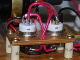
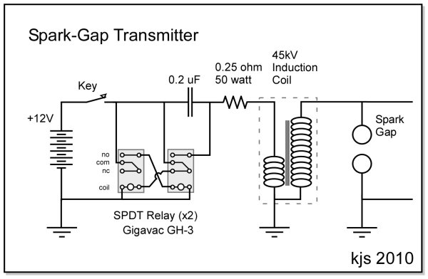
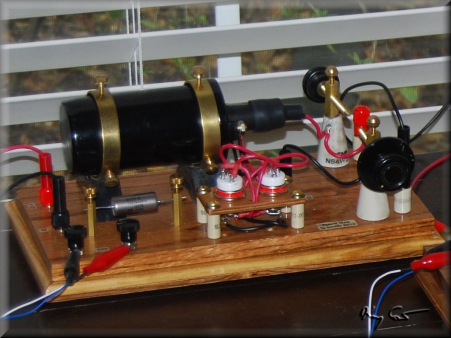
Circuit diagram of the power module indicating the wiring concept for the two-relay solution. And finally, a photo of the set with the two relays in position and ready to go.
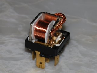
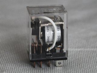
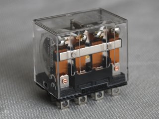
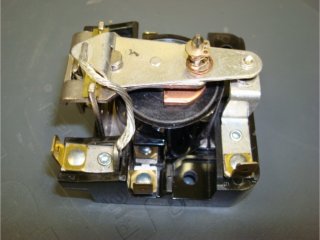
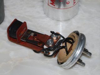
Finally, a small gallery of relays, and even an old auto vibrator that were tested in my quest for the ideal interrupter.