The design for the transmitter starts with a notional target transmission frequency and the design equations from two primary sources: Fleming, 1910, The Principals of Electric Wave Telegraphy and Telephony., and Bucher, 1920, The Wireless Experimenters Manual. Additionally it requires some estimate, guesstimate really, of the antenna distributed capacitance and inductance.
As the project is demonstration only, I have selected a frequency at the low end of the HF range just above the MW broadcast bands. The designs in the 1920's typically aimed at about 200m or 1.5 MHz. To keep my design close I chose 120m, or about 2.5MHz. It is a fairly quiet part of the spectrum. Keep in mind this is a notional project not intended for actual broadcast. I used charts and data presented in Bucher to imagine an amateur inverted L antenna with about 20 uH distributed inductance and 150 pF distributed capacitance. As antennas are magical mystical things that nobody (meaning myself) really understands this appears entirely reasonable. In any case, the transmitter is tunable to bring it to proper resonance (hopefully) when attached to an actual antenna. These then are my fundamental design parameters:
Design frequency = 120m
Antenna Co = 150 pF
Antenna Lo = 20 uH (20000cms)
La = Lo/3 = 6.67 uH (6667cms)
L1 = Loading, or secondary coil = ?
From Bucher:
Wavelength = 59.6 sqrt((L1+La)*Co)
Assuming a design frequency of 120m and solving the above equation for L1, I find:
L1 = 20 uH (20000cms)
20uH then is the value we wish for the oscillation transformer secondary winding.
For the primary winding we find in Bucher the following useful equations:
L = lambda^2 / 3550000 * C, and/or
C = lambda^2 / 3550000 * L
Therefore one starts with lambda = 120m and then either assume a capacitance or an inductance. For this project I found a good match with 2000 pF and 2 uH. To be safe both inductance and capacitance can be varied around these two design numbers.
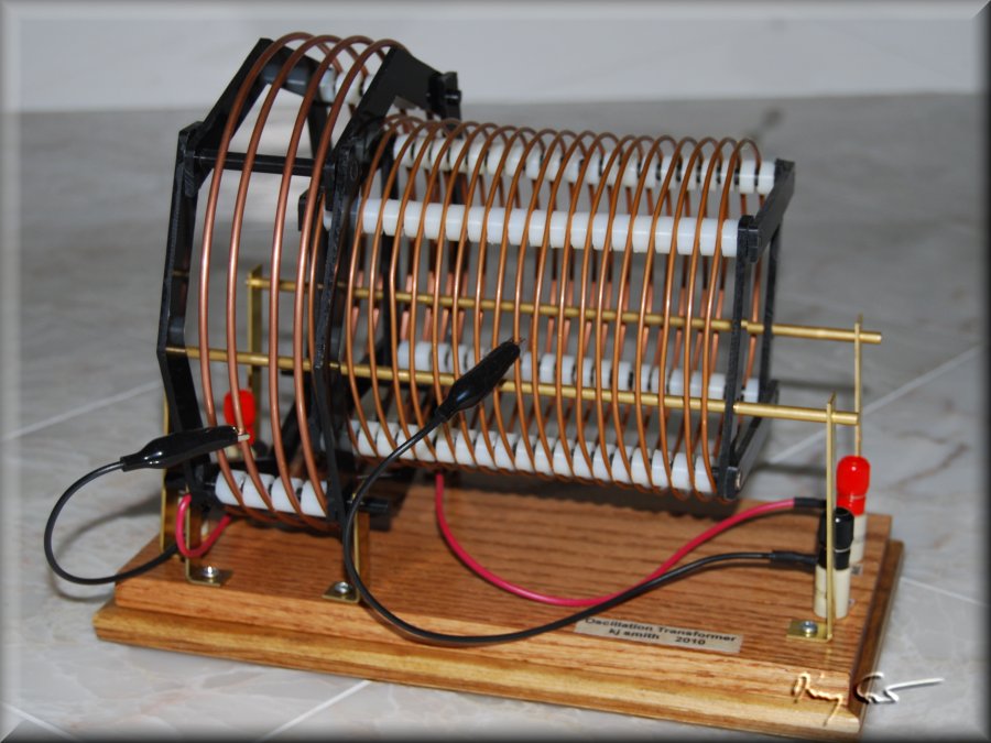
The oscillation transformer design thus becomes a matter to choose coil lengths and diameters to give a range of values inclusive of Lsecondary = 20uH and Lprimary = 2uH. To make the transformer loosely coupled the secondary needs to slide within the primary. I chose the following parameters:
Primary: Diameter = 7", Length = 2.0", Turns = 4, uH = 3.81 max, 1/8" copper tubing
Secondary: Diameter = 5", Length = 6.0", Turns = 22, uH = 27.4 max, 1/16" copper tubing
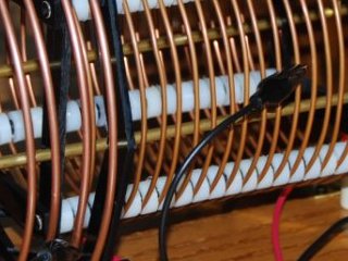
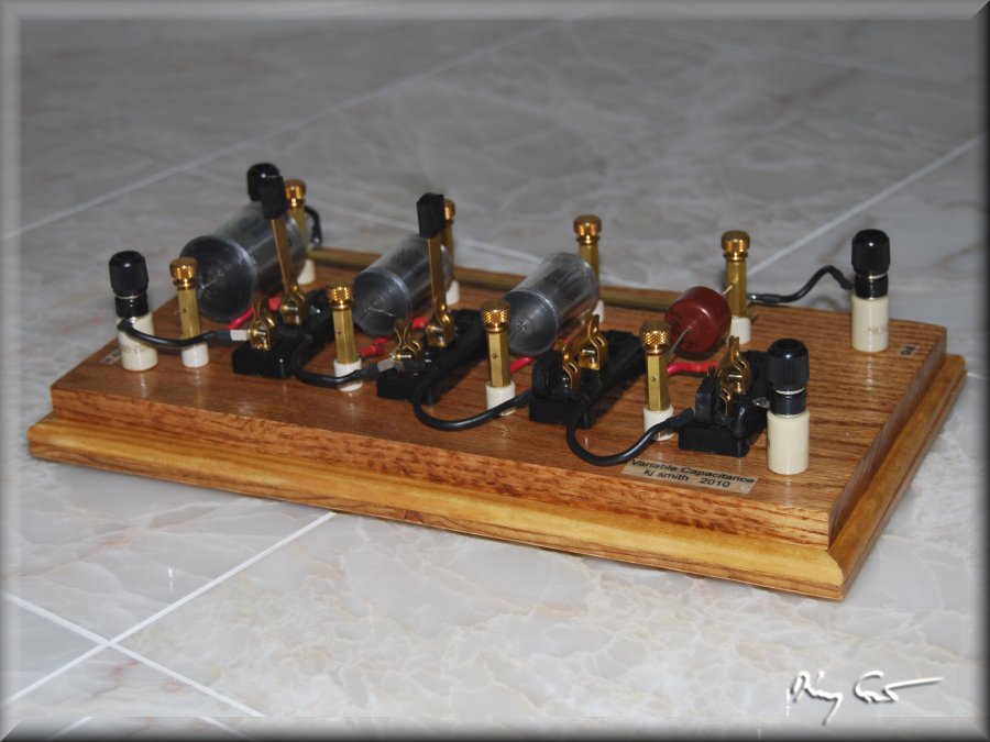
The capacitance module simply consists of high-tension modern capacitors switchable into or out of the circuit in parallel. The original intention, still in play, is to use Leyden Jars, but that is another matter. The four capacitors have values of 500, 1000, 1000, and 3000 pF giving plenty of combinations to choose from. Changing inductance is a matter of clipping to the coil at the right place. Finally, coupling the coils is a matter of sliding the secondary along rails into or out of the primary winding. The following photos give portraits of the two oscillation circuit modules.
When one walks into a room, nothing quite says "Transmitter present!" like a big oscillation transformer!
