Powered by Fleming's amazing valve
Crystal radio circuits come in a seemingly endless variety of forms and possibilities. That and the historical context of their importance at the dawn of the radio-age makes them a fascinating hobby. I enjoy making these radios, learning and exploring new and interesting circuit ideas, incorporating vintage components into my sets, and finding historical connections between the radios and the fathers of the technology.
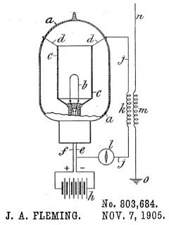 My latest project involves a passive receiver rectifying the signals with a vacuum diode. Professor John Ambrose Fleming had consulted for Edison Electric in Britain and had experimented extensively with Edison two-electrode bulbs in the 1880’s, presenting his results on the “Edison Effect” to the Royal Society of London in 1889, and the Royal Institution in early 1890, and finally his definitive paper to the Physical Society of London in 1896. Later after the turn of the century he began consulting for Marconi seeking better mechanisms for radiotelegraphic detection of radio signals. Most avenues of research proved futile until he recalled his prior work on the Edison Effect. He literally retrieved the original bulbs he had experimented on previously and set up a test to apply the effect for radio wave rectification. His experiments were certainly successful. This idea proved a novel and unanticipated use of a prior-known effect amounting to true discovery and thus was awarded British (24,850) and American (803,684) patents in 1905, these successfully defended against De Forest’s subsequent infringements. Pondering this interesting history, I began wondering about the Fleming diode and thinking, in crystal radio, this is not amplification, so why not? Also, one must consider the glow, oh the glow… I just had to build this.
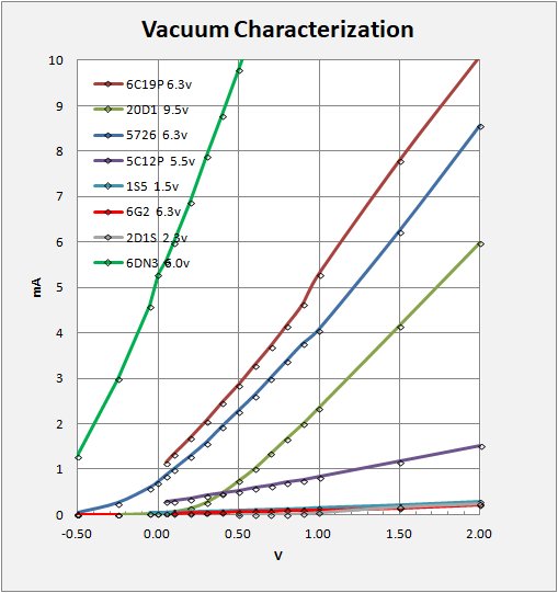
Finding a correct tube for the project is a bit of a story in itself. I have never worked with tubes and, while it appeared natural that diode tubes ought to exist as well as triode/pentode/etc (they do), I had no idea what tube was what nor how to know what would work for radio rectification. Many diode tubes I found are for power supply work and may not be appropriate for radio detection at all, (actually they work fine). Jumping into the search both feet, I waded through the datasheets of many/most diode tubes to get to know them well enough to choose. Additionally I purchased a small variety of tubes for testing. The results of this study are discussed in full under the Radio Lab : Diode Test section of my page. Of all the tubes tested, I finally chose the Russian 6C19P as the tube having the most sensitive characteristic and a handsome appearnce. The tube is a power-hungry beast though, (1.1 Amp current draw at its rated 6.3 V), and this radio requires a power supply, but its worth it! The following graph plots the characteristics of seven tubes I tested for the project.
While the project radio was to feature the Fleming valve, I naturally wish to have an interesting circuit as well. As always, it would be a breadboard set and single tuned for ease of use. I also wished to utilize and test Dave Schmarder's selectivity enhancement circuit (SEC) in the set. This last item to compensate for the typical poor selectivity in single-tuned circuits. One circuit that caught my eye from an early time was Modern Radio Labs' MRL#2 set. To this set I would add the SEC modification. In such configuration I notice that it bears a remarkably close resemblance to Set #6 in W.J. Mays' Boys Book of Crystal Sets (BBCS). The MRL#8 set also shows design affinities and includes the choke missing in MRL#2, a fact noted by Mr. Osterhoudt himself. In the end my circuit design, shown below, must be considered a close, (but not exact), member of a family of radio circuits consisting of MRL#2, MRL#8, and BBCS#6.
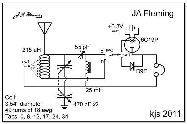
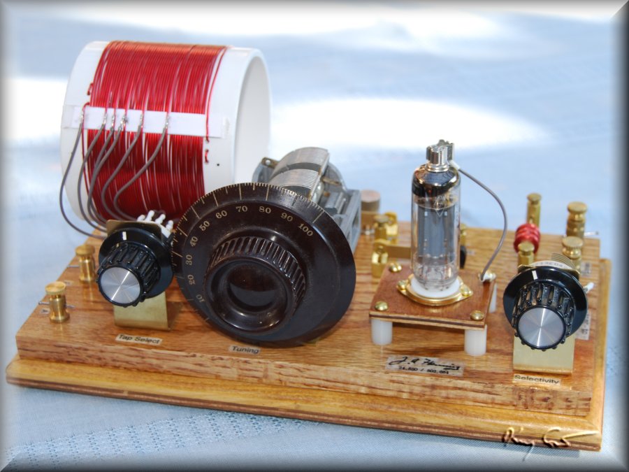
The actual set with its controls, taps, tuning and SEC shown below:
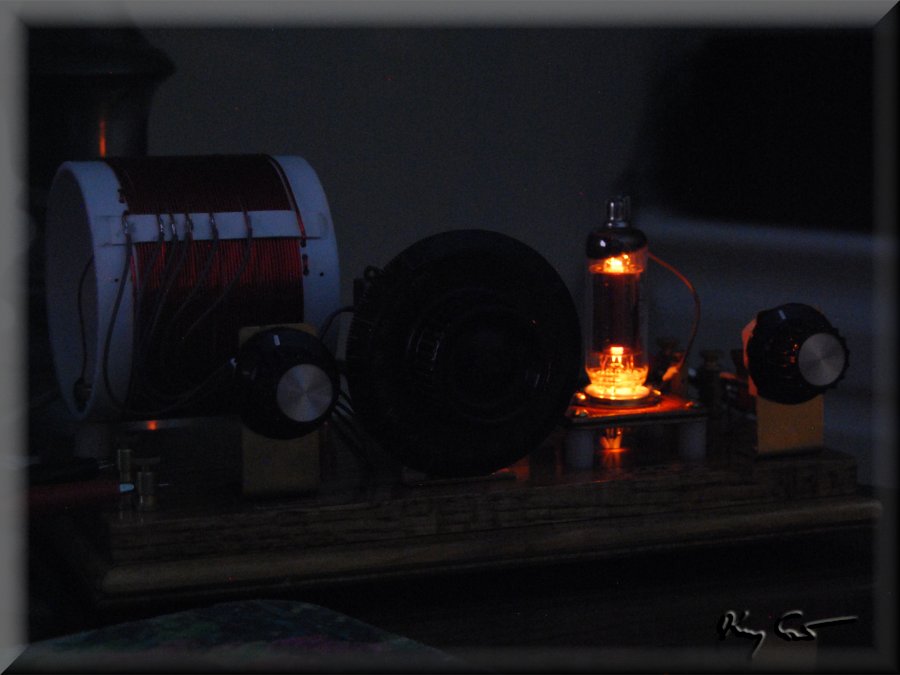
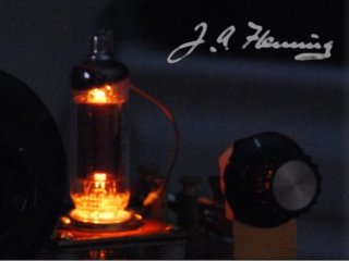
The glow.... Oh the glow!
PERFORMANCE:
So, is is a keeper? Does it perform well? Is Fleming's valve a revolution? The following tests answer all these questions and them some. We start by noting from the circuit diagram above that this is essentially two radios depending on whether it is switched in the Narrow or the Broad setting. Importantly, in the narrow position the SEC option is essentially out of the
circuit. This will be seen in the measurements as well. A note here, all measurements were made at a nominal 1100KHz with a signal generator and the output of the generator was a sine wave with 2.0V p-p. This is a strong signal and may impact the results, especially concerning sensitivity, but it makes for easier measurements and ready comparison between sets. For this set I made identical measurements with both the diode (Russian D9E, a 1N270 equivalent) and the tube/valve (Russian 6C19P) in place.
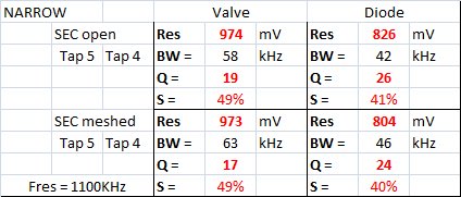 Looking first at the radio in the Narrow switch setting. The table at left indicates the peak output DC signal in mV at resonance, the measured bandwidth at -3dB above and below resonance, calculated radio Q and Sensitivity (Sensitivity here is simply 100 * DCout / ACin). The table shows that the SEC circuit itself provides no change in performance. This is expected as noted above, the SEC doesn’t impact the circuit in the narrow setting. I ran the valve at 6.3 V on the heater filament and am surprised to see that the radio sensitivity is higher with the valve than with a diode. Dissappointingly, the valve had a poor effect on the radio Q, going from Q = 25 with the diode to Q = 18 with the valve. I have to imagine the valve has a rather different impedance / capacitance characteristic from the diode. Still, the good sensitivity is pleasing to see.
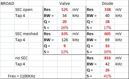 Looking at the performance in the Broad setting we find the SEC has a definite impact. As before, the valve has higher
sensitivity than the diode, but here we see a classic tradeoff between sensitivity and selectivity. Turning the SEC to
its maximum selective position (lowest capacitance) helps, (Q increases from 9 to 20 with the valve) but at the price of lower sensitivity, (Decrease from 32% to 26%). More disturbingly, the overall sensitivity in the broad setting, which ought to be higher than in the narrow setting, (that is, greater than 40%) is quite the opposite, (less than 30%). Additionally,
setting the SEC to its most selective position merely returns the radio to a selectivity already found in the narrow
setting (narrow Q = 18, broad Q = 20) while lowering the sensitivity. So, I consider the SEC in this circuit a bit of a failure. My suspicion is that the insertion losses associated with the SEC are damaging and no real selectivity boost is given that was not already found in the narrow setting. To address this, I removed the choke and minimized the capacitance of the SEC, effectively removing it from the radio. Re-testing the radio now showed a return to good sensitivity and moderate Q. Actually, with this test I see virtually no difference between the Narrow and Broad performance. Oh well... At least I understand now why Osterhoudt removed the choke from the MRL#2 set.
Looking at the performance in the Broad setting we find the SEC has a definite impact. As before, the valve has higher
sensitivity than the diode, but here we see a classic tradeoff between sensitivity and selectivity. Turning the SEC to
its maximum selective position (lowest capacitance) helps, (Q increases from 9 to 20 with the valve) but at the price of lower sensitivity, (Decrease from 32% to 26%). More disturbingly, the overall sensitivity in the broad setting, which ought to be higher than in the narrow setting, (that is, greater than 40%) is quite the opposite, (less than 30%). Additionally,
setting the SEC to its most selective position merely returns the radio to a selectivity already found in the narrow
setting (narrow Q = 18, broad Q = 20) while lowering the sensitivity. So, I consider the SEC in this circuit a bit of a failure. My suspicion is that the insertion losses associated with the SEC are damaging and no real selectivity boost is given that was not already found in the narrow setting. To address this, I removed the choke and minimized the capacitance of the SEC, effectively removing it from the radio. Re-testing the radio now showed a return to good sensitivity and moderate Q. Actually, with this test I see virtually no difference between the Narrow and Broad performance. Oh well... At least I understand now why Osterhoudt removed the choke from the MRL#2 set.
Q for this single-tuned radio is comparable to other radios I have built. This is a circuit demonstration radio
presenting Fleming's valve. Nor have I finished with the SEC concept. The circuit utilized here is not ideal for the SEC, ground is taken off the top of the coil, its an odd, if interesting, configuration. I will give the SEC another shot with some other radio. Overall, I am very pleased with the set and enjoy listening to the local Spanish music format station with the warm glow of the tube keeping me company. Oh that glow....
Ciao!

02 / 2011